![]()
|
|
|
Handwritten code made with EditPlus3
| A collection of radio oriented diagrams, add-ons and designs |
Always busy all those years ............... |
|
|
|
©CopyRight, modifications add-on design, drawings, photographs,
gal programming, and research by: W.A.J. Geeraert ( PE1ABR ) email
Click over HERE for some utilities![]()
to work with old LAYO1 and ORCAD for DOS.
All the work you find over here has been made with it!
Almost all the drawings are made available in PDF format.
You MUST have Adobe Acrobat reader  installed, see at the bottom of this page.
If problems: copy PDF files to harddisk first without double click, but with "copy to" option.
AERIAL SUPPLEMENT / THE LOOP PROJECT:
|
This loop aerial uses the same principle as a small 10 x 10 sq. cm coaxial EMC pickup-loop coil. If we make that loop as hughe as possible (150 sq. meters !!! in my case) we could use it as a wideband receiving aerial, working already from very low frequencies. Much amplification was needed for a usable Rx result. But then it works great!
PDF with the latest high dBm amplifier |
 An early version with 2 P8002 power FET's The old drawing for the above Amp |
 The latest version according the drawing with J310 and 2N3866 |
|
A Dutch text written by me about this loop was published by the Dutch amateur radio magazine ELECTRON februari 1999 , now in original PDF print quality on my Home Server. The above is available in Dutch only, but the original article has been referred to in English in UK Radcom April + May 1999 The above link brings you to an English PDF version of the Radcom articles (200 KBytes) An anthology of all Dutch-language publications in the VERON monthly magazine Electron can be found on my NL page VERON A PRESELECTION TUNER SKETCH FOR THE LOOP:
PDF with publication in Electron Febr. 1999 and Radcom April+May 1999, the additional 136 kHz filter For a good receiver as the NRD-515 sufficient extra preselection with only this device. |
ACTIVE E-FIELD AERIAL PROJECT:
|
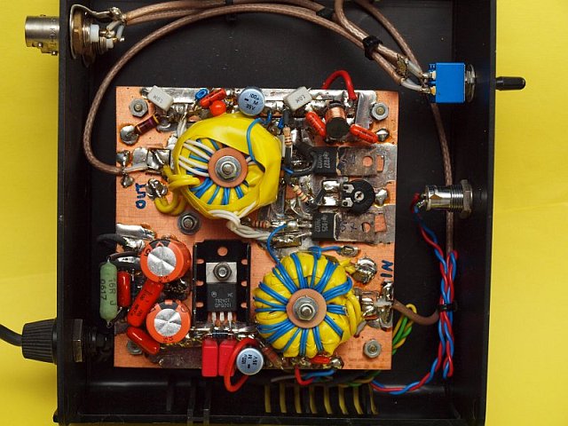
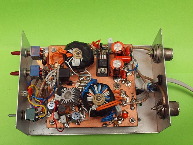
The basic idea behind this project was to make a good active aerial with a very high intercept point, especially for those frequencies where a normal (too short) long wire was not good enough. Optimised for frequencies from about 10 - 50 kHz to about 10 - 25 MHz. So longwave, beacon, medium wave a.s.o. It is basically a symmetric (balanced) circuit that is used a-symmetric. By varying the class-A current and at the same time varying the balance too, a point can be found where the two FET curves are mirrors of each other. If tested with heavy overload, this point is the point with minimum cross-modulations, it cancels out!! I use a two tone test generator with 2 and 3 MHz, and cancel out 5 MHz. See an item below. Because 5 MHz is NOT in the original signals. The generator I've created is crystal controlled so the signals are in phase, nice view on scope, up to 10Vpp linear HF on the primary of the transformer!! |
PDF with Circuit diagram of the early first public 1996 version (only in Dutch) Now abandonned due to unavailability of the VHF power-FET semiconductors. PDF with circuit diagram outdoor active aerial unit and now / en nu: NL versie PDF with layout component side CAD outdoor unit PDF with layout solder side CAD outdoor unit PDF with outdoor unit mount and now / en nu: NL versie PDF with circuit diagram power supply unit and now / en nu: NL versie PDF with layout component side CAD indoor unit PDF with layout solder side CAD indoor unit PDF with PSU board mount and now / en nu: NL versie PDF with layout mainsfilter PDF with mount mainsfilter PDF with front and back panels indoor unit PDF with mounting overview all components power supply unit |
  Click for surprise! |
PHOTOGRAPHS: Page with nice new photographs active aerial system Page with some re-scanned EMC/ferrite related photographs Click for my adapted version of a MFJ phasing unit, made suitable for beacon reception and medium wave band |
 Only one unit is equal to none! With more you can add directivity with a phasing unit! |
| Now some Radio add-on hardware, aerial and EMC info, diagrams and photos |
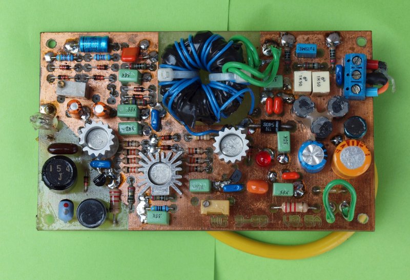
IP3/IMD duo-frequency test signal generator
|
This circuit generates several strong single or duo-tone HF test frequencies derived from 1
crystal oscillator to overdrive HF amplifiers. By setting the AC input level and multiple DC currents or voltages in
the connected HF test circuit, you can see which settings have the greatest effect on the creation of
unwanted mixing (sum-)products. The multiple generator signals are "stationary" on the scope
because they come from the same main oscillator.
Available are 200 and 300 kHz duo tone, 2 MHz and 3 MHz duo tone and 3 MHz with 40 kHz duo tone.
There is strong "resonance" filtering per frequency before the mix, but 100% without harmonics is
difficult. However, the sum of the two duo tone frequencies is NEVER present. By tuning in to this
sum on a narrow filtered test Rx (and suppressing the original signals), e.g. 500 kHz or 5 MHz, with heavy overdriving you can set the test circuit settings so that those unwanted mix product signals are minimal or GONE! This is possible with my active antenna circuit (see above), for example. By setting the total current and also the ratio per balance branch, there is a point where the sum mix signal is minimal or even completely gone. The FET curves with some non-linear curvature then
become the exact "mirror image" of each other. The output signal hardly changes and is then almost
10Vpp distortion-free on the primary of the output transformer!. |
|
Here is the drawing in PDF. |
 Here are the filters for the narrow band filtering in the generator unit |
 This "narrow" filter unit extracts only the distortion = sum frequencies of 500 kHz and 5 MHz |
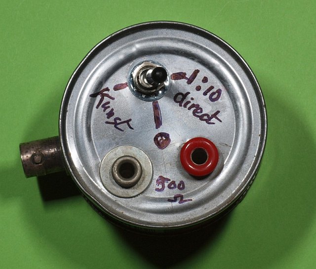
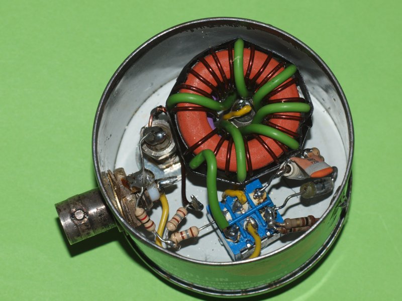
GENERAL COVERAGE RECEIVER AERIAL T-PIECE (RF-SPLITTER)
|
This is a modified copy of a Radio/TV splitter adapted for the frequency range of a general coverage receiver. Works with perfect separation from lower than 100 kHz to at least 15 MHz. (This is something else than signal pass-through, that works to 50 MHz.) With extra care and an extra compensation capacitor the separation specifications are valid up to 25 Mhz, but pass-through drops to 35 MHz. Mounted in a small tin-can previously used for purée of tomatoes! Intended to connect an aerial to two receivers with very low mutual influence. Signal drop about 4 dB, mutual suppression more than 25 dB. It can also be used to connect two aerials to one receiver, it will reduce QSB. But it can also cause cancellation on a rare single frequency, so be carefull! DC pass-through (2 active aerials...) is also possible with an extra capacitor in transformer ground. I don't think that's a good idea, because the DC current has a negative influence on the self-inductance value of the ferrite. Wound with using double wire (on the Z-transformer core only) gives a little lower leakage inductance. PDF is simple drawing. |
|
Here is the UK splitter drawing in PDF. Or drawing in a Dutch PDF. |
Click to enlarge the picture |
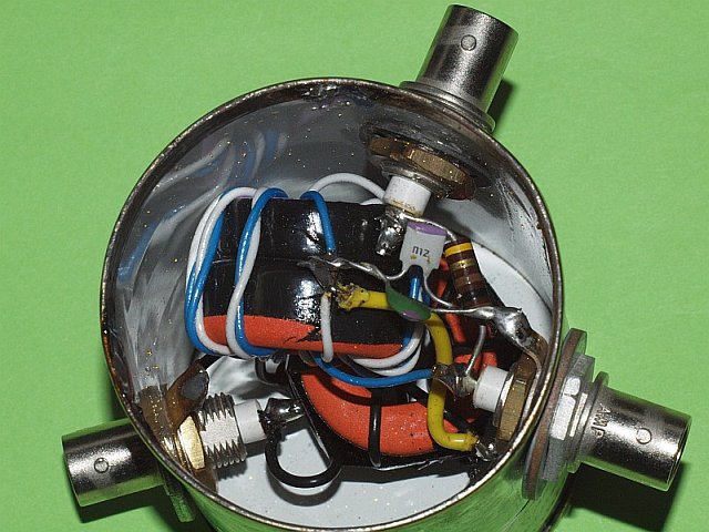 |
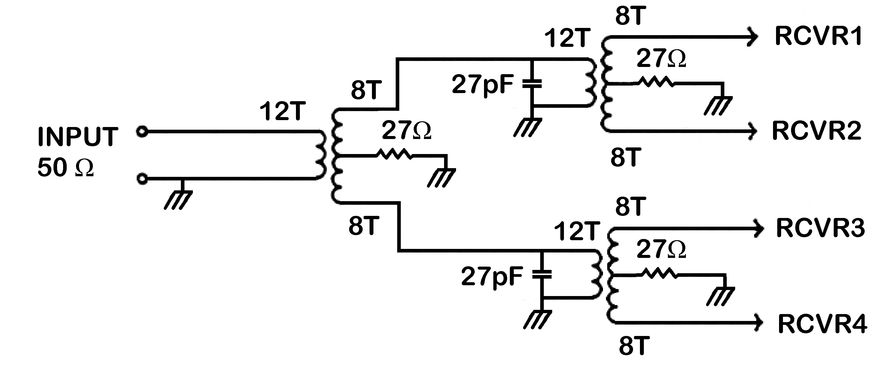
FOUR-PORT GENERAL COVERAGE RECEIVER SPLITTER
This is a splitter based on a different principle with only three cores in total, only one core is used to split in two. Based on a principle also (re-)published by John Bryant and Bill Bowers: Rolling your own splitter. Or from my server With three toroid sets you first split in two with the first set, and afterwards you split both outputs another time in two. Result: a four output port unit with only three toroid sets. Keep in mind that this is the practical maximum without the need for additional amplification. A least you reduce the signal with -6 dB. For stretching the pass-through frequency curve it was handy to add a small capacitor in between both sets of toroids. A gradual decay in signal is equalised with the capacitor to above 30 MHz, above 40 MHz it now has a dip. I've choosen 2x 27 pF to obtain an equalised pass-through. The cores used for each duo-core-set are: ex-Philips 23 mm 4C65 (purple) AL = 82 and an old 23 mm core comparable with Philips 3H1 (red + yellow) AL = 1850. Or use for the high AL core a 23 to 29 mm 3F3 (blue), 3C85 (red) or 3C11 (white), with an average AL between 1000 - 3000. Same size FT 82-77 is also usable. Due to the rather low high-AL core a good Q and lower losses during tests. A little more windings are needed for 50 ohms to reach about 100 kHz as the lowest frequency, if you compare it with orange 3E25 cores. 50 ohm side turns: N = 12, split side: N = 2x 8 bifilar. Usable from under 100 kHz to above 30 MHz. This version is build in a fish tin as you can see....... It only smells if you connect a transmitter to it (HI). |
||
|
 |
 |
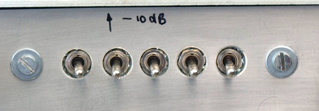
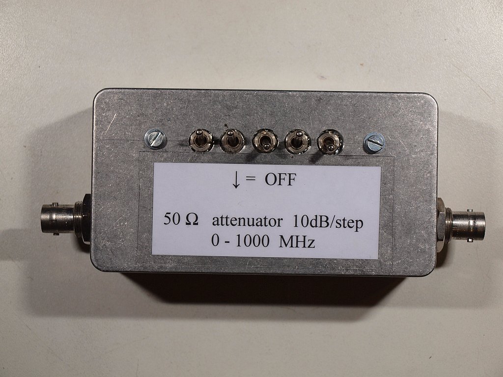
A STANDARD PI-ATTENUATOR NETWORK BOX, plus.......
|
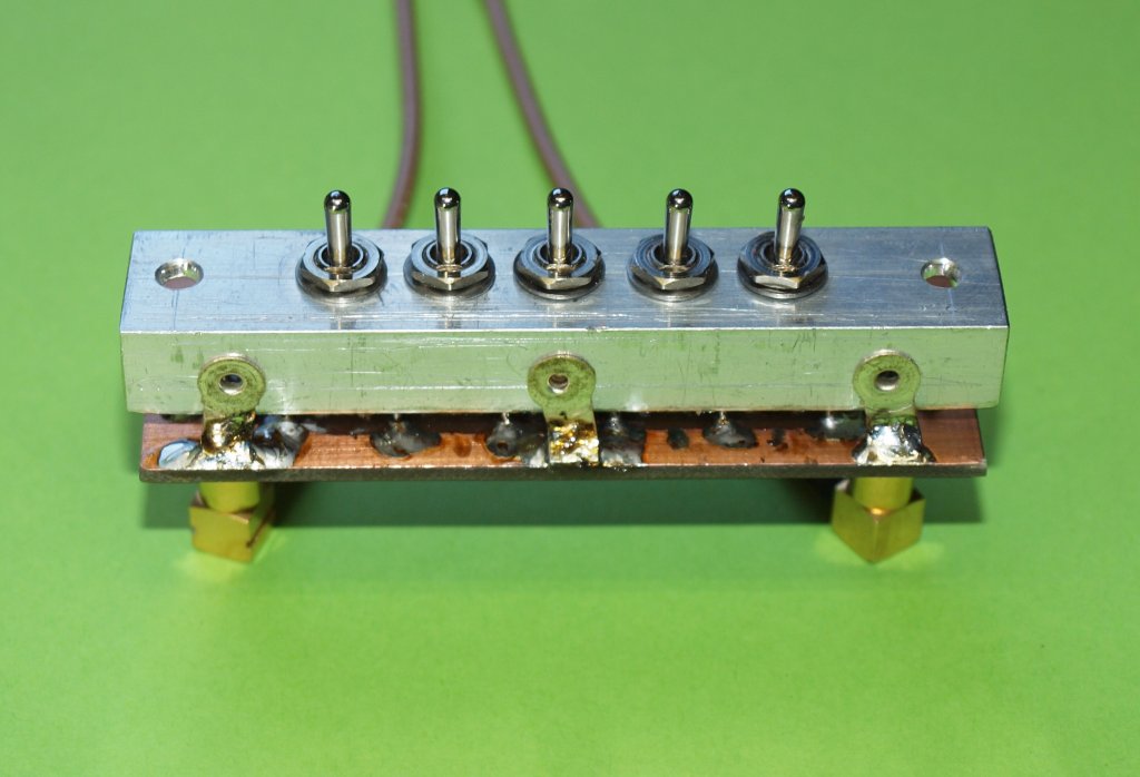
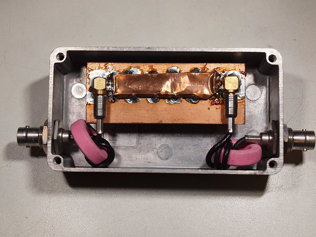
This is a standard attenuator network like everyone builds them. Nothing special. But please keep in mind that the resistor wires should be as short as possible. After a few -10 dB networks leakage becomes a problem. So screen the sections from each other. See pictures, works up to 200 MHz. If you want to do it much better, you should make it in SMD, and with much more screening. That's special!! It will work perfectly over 500 MHz!! Although it is a hell of a job to make it..... More than 5 sections ( = -50 dB !! ) is still unwise due to leakage, use more units then if you need it. |
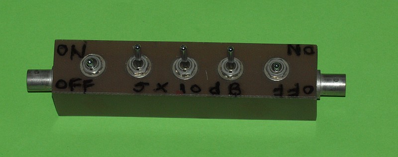 Top of the PI-sections. Click to enlarge the picture |
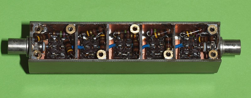 Inside of the PI-sections. Click to enlarge the picture |
 And in SMD! Click to go to a special sub-page about this device |
||||
 A different SMD version Click to enlarge the picture |
 The SMD version in a table box Click to enlarge the picture |
 The inside of the table box, with extra common mode suppression. |
A TUBE RADIO RF-GENERATOR CORRECTION NETWORK
(ARTIFICIAL AERIAL NETWORK)
|
This is a dual "impedance correction network" to be connected between a RF-generator with low impedance and a common (old) tube radio with higher-Z "wire aerial" input. One branch is a simple 1 to 10 impedance transfer. The other branch is an artificial wire aerial simulation circuit for a common home wire aerial. It is needed during RF circuit alignment. Using a blue 3F3 (equivalent to FTxx-77 material) or white 3C11 toroid in place of the orange 3E25 is less lossy. Using double green wire proved to be better too, it gives a lower leakage inductance. The PDF is a simple drawing. |
|
UK drawing in PDF Dutch PDF The curve is NOT taken when connected to a radio set, but when loaded with a 500 - 600 Ohm test resistor. |
 |
 |
 |
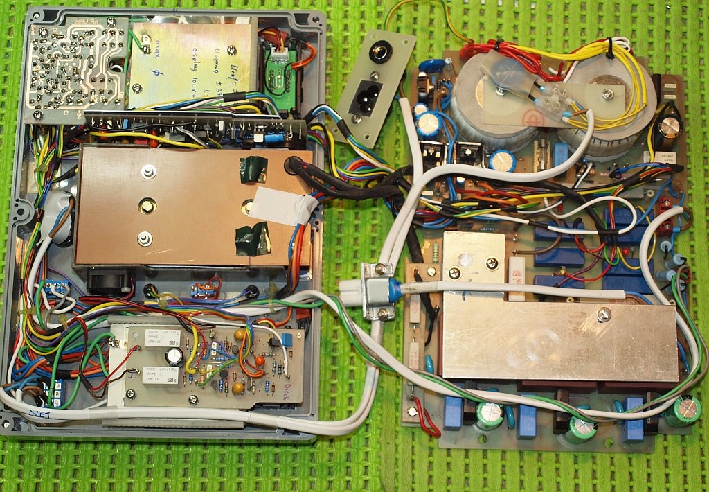
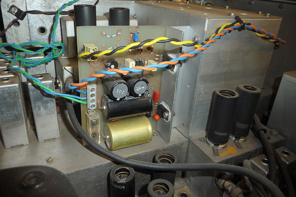
A SPM-30 SURROGATE BACKLIGHT OPTION
This is designed to give better readout of the LCD display of the Wandel & Goltermann SPM-30
|
The SPM-30 is made for battery operation, so to reduce power consumption NO display or scale illumination is present. Unfortunately the LCD display is hard to read in low light conditions. You always need an extra "desktop" lamp nearby. I designed a very simple lightguide construction with a piece of Plexiglass (Perspex) with a 90 degree reflection angle. The light comes from four 3 mm white high brightness LED's in series at the other end. They are glued in the plexiglass. Current consumption is about 10 mA from the unstabilised power with a currentsource stabilisation circuit placed in series with the four LED's. The currentsource circuit is probably not needed anymore. In my case I had a large variation in unstabilized voltage due to an error that wasn't solved yet. Now it is. See C-series remark, the 1.5 V zenerdiode in the shortcircuit currentlimit was in error. One picture below gives a very low light picture ("creamy" colored), but perfect readable LCD display. On the second picture you see how the plexiglass is mounted behind the PCB board on threaded M3 stand-offs and a few washers. The PC-board acts hereby as a light diffuser!! It's not perfect, but performs remarkably well without any display board modification. The "green chewing gum" contains the currentsource circuit. Its input is connected to the ON/OFF switch to the wire that goes to SK1-F. Ground goes to the mains LED ground nearby. The PDF is a simple pencil construction drawing. I used 6 mm material. For 8 mm you probably have to reduce the height of the standoffs. |
|
Plexiglass drawing in PDF For hardcopy use. Old version "C-series" PSU circuit Circuit D9/D10 is different. |
 Electrical circuit Click to enlarge |
 |
 |
A set of Mono or D-cell's for my SPM-30
|
Recently I bought a lot of large mono / D-cell NiMh rechargeable batteries for my old
SPM-30 levelmeter from Wandel und Goltermann. Batteries purchased at the local Lidl
supermarket. By itself they comply with what I was expecting, they work.
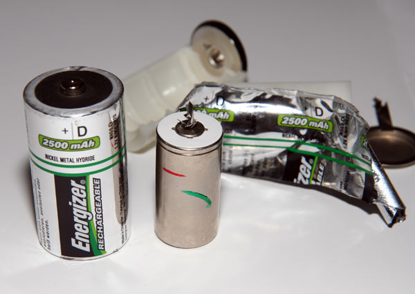
In some batteries there is something rattling inside if you shake them. How is that possible? I put a plumbing pipe cutter on the one with the loudest rattle. Great was the surprise. Inside the mono cell just three small AA penlights were in parallel! See the rightmost picture. I emailed bigclivedotcom and his answer was: |
||
|
It appears that it is nowadays the habit: almost all cheap recharcheable D/Mono cell's are FAKE!!!! |
||
|
Inside is - depending on the on-printed capacity - a C-cell, or 1 to 3 AA penlights in parallel, or a dust-buster (mini C-)cell. Beware of fraud! There are also expensive D cell's that are also fake. If you might think the expensive ones or a real brand like Duracell or Varta are "the real thing", you could be very disappointed. A D cell with 3500 mAh or lower is scam!
So NO, sometimes those brands also are NOT real D-cell's!! Look at the low mAh capacity in the examples below. The only way to know before you buy them is: is the mAh value between 8000 and 15000 ? Or put them on a weight scale to determine the weight. Are they filled with air/plastic or chemicals/energy?. Fake rechargeable Mono or D-cell batteries with air or plastic inside are between 50 - 80 grams a piece, real 10000 mAh versions above 150 grams! On a site like Conrad or Reichelt you can fetch a PDF with info, the weight is mentioned! Real D-cell's are very expensive, 20 - 25 euro's each! |
|
A site about fake D-cell's that wants to be linked. The first leftmost image is from their site. A Video from YouTube, a bit long but nice to see the peel off of a fake/scam battery. |
 Hilarious, this D-type has 2500 mAh inside, less than a quarter. YES, Four times more would be realistic. Scam! |
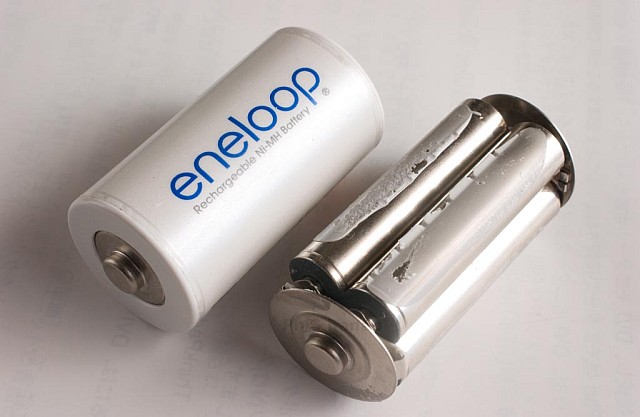 The Eneloop C-cell is composed of 4 x AAA cells, the D-cell is composed of 3 x AA cells. |
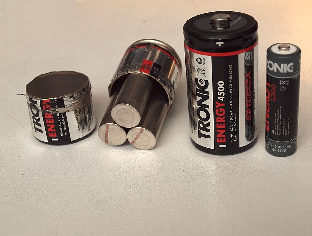 Not the worst, this type (Lidl) has even three penlights inside. Only 4 euro. And even 4500 mAh. Although there is some waste over time, not all prove to be OK in the long run. |
 Hilarious, this D-type also has only 2200 mAh inside. At least four times more would be realistic. Pure Scam! |
 Also hilarious, this type has 3000 mAh inside. Should be 3 times more! |
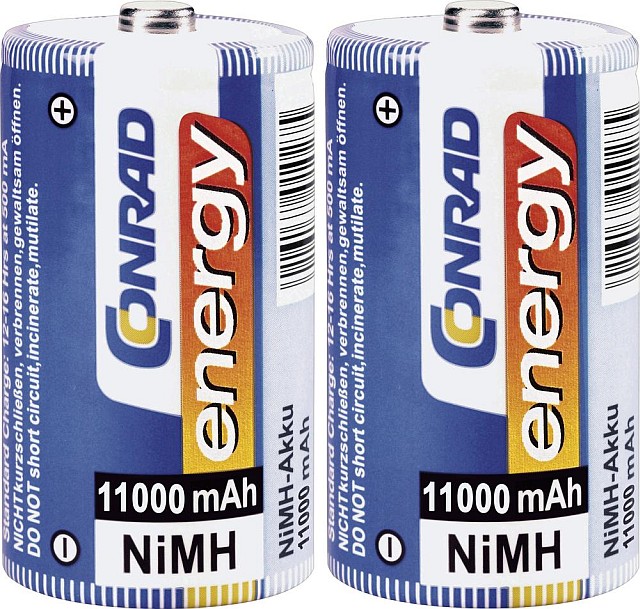 Expensive, 20 euro each, but 11000 mAh inside. |
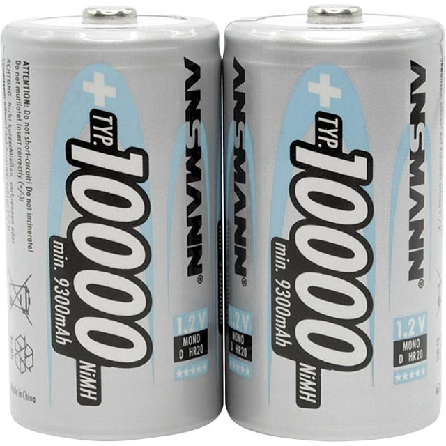 Expensive, 24 euro each, but 10000 mAh inside. |
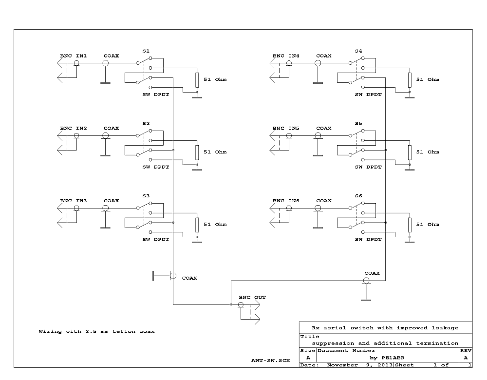
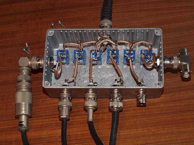
A SPECIAL Rx AERIAL SWITCHBOX
THIS VERSION HAS MUCH HIGHER LEAKAGE SUPPRESSION
|
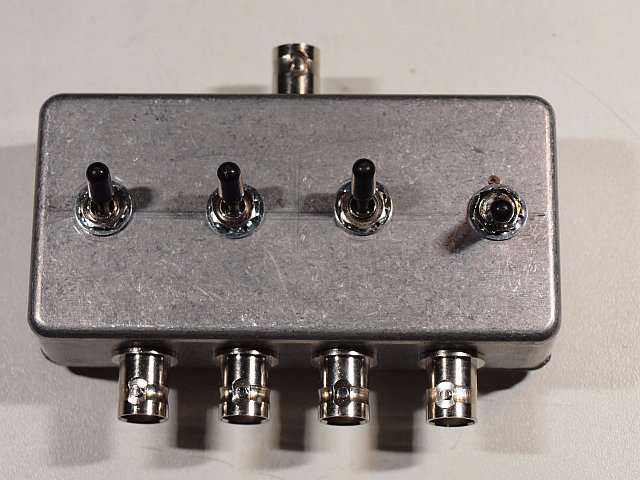
This is a non standard HF / Shortwave Rx switch. If an input is NOT selected it is terminated with 50 ohms. Also the switching is with a double pole switch, if an input is NOT selected the connection between switch part-1 and switch part-2 is grounded. All the internal HF wiring is with 2.5 mm teflon coax. Of course all is mounted in a 100% HF-tight cast aluminum box. The PDF is a simple drawing, the highres original of the PNG. |
|
Drawing in PDF Click unvisible drawing right to see a larger PNG version. For hardcopy use the highres PDF. |
 |
 |
 |
|
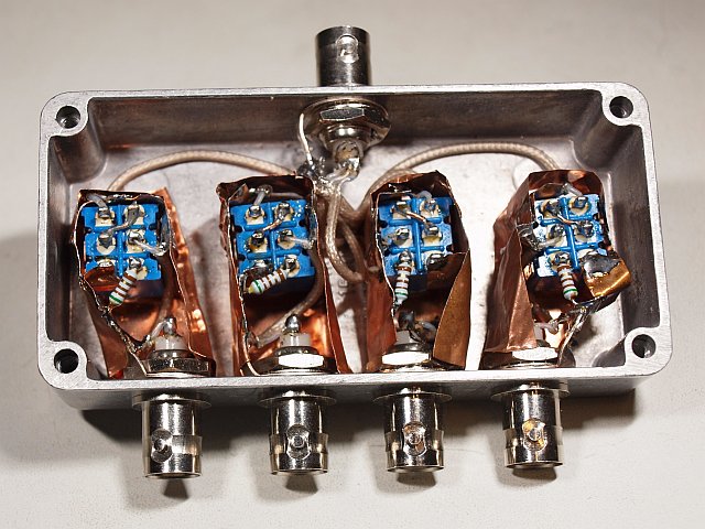
In this row an optimised aerial switch version for a VHF (or HF) radio. Still too much leakage (in the pictures above). In this version all the switches are individually screened with copper foil. The small pieces of connecting coax form an unwanted parasitic set of resonant stubs. But they are only active on higher UHF frequencies, and give strange dips....... This makes it useless above 350 - 400 MHz. |
 |
 |
At last a stable 12V power supply for the portable MFJ-266 analyser
|
For my MFJ-266 RF analyzer I had put together a NiMh battery pack with cheap Lidl batteries. With normal 1.5V alkalines it was always hassle with the voltage that always dropped too fast and was never actually the real 12V. With NiMh batteries in it is actually completely wrong, now max. only 10 volts available. Because of the voltage stability therefore 4 more batteries are used and a compact DC voltage PCB designed and built in for the charging adapter, charge currentsource circuit and a 12V low-drop regulator. First opted for the L4940V12, which I still had. That turned out to be a bad choice. Due to the available space, the cells are placed in a few separate battery containers. 2x 4 pieces slightly more compact than the original with batteries in the width and 1x 2x2 pieces in the length, makes a total of 12 cells x 1.25 V = 15V. It just fits. With a very full battery 12 x 1.4 = 16.8V. With a very discharged one 12 x 1.1 V = 13.2 V. In other words, with a special low-drop regulator, the 12 V now remains nice and OK. Because of charging /refreshing the batteries via a current source coupling circuit, I also connected a DC adapter. All fine. Until I, via a duo TO220 Schottky power diode (loss only 0.3 V) in front of the regulator, I also wanted to work via the adapter as a power supply. Battery via one diode to the plus IN low-drop, adapter via the other diode. See diagram link below. Adapter voltage is 20 to 22 Volt without load. EXIT. No more 12V output voltage. Adapter disconnected, 12V returned and it worked on the battery again. Shit. After much grumbling and many datasheets thoroughly read: this L4940V12 low-drop can have a 30V input voltage without damage, but switches itself OFF above 17 Volt input voltage (about 18V in my case). What a shitty thing. I hadn't planned that. After some searching in the stock boxes it eventually became a Linear Technology LT1086CT-12 low dropout, which I also had. However, this cannot be directly soldered on the PCB, which was already finished, due to a different pin connection order. Then connect it with a few wires, the LT circuit works as I expected by the way. At second thought, another low-drop, the LM2940T-12, would have been more convenient, it does fit on the PCB as it is now. The adapter has since been replaced by a 19/20 V old Dell laptop power supply. And as some kind of internal protection a 4 to 5mm sheet of stiff packing foam is added between the original board and all the batteries. A 3-position changeover switch and a duo-color LED are built into the front panel. Operation: Charge (red) - Off - On (green). Some tested DC adapters had a too high AC ripple. So later an extra electrolyte (470 to 1000 uF / 35V) was added on the adapter input pins on the PCB, as can be seen on the picture. Before you start with any changes, first solder a heavy diode (2 - 3A) in reverse on the MFJ board over the voltage inputs. Or also temporarily add a 15V power zener. It prevents a blown-up device if you make a mistake during changes!!! Available for download: The CAD files. The draft drawings. |
 The front view of the box And exactly 12V, the whole charge time |
 The extra power supply board And the added extra electrolyte left |
 Some more batteries The extra 4 battery holder just fits |
The also available AW07A SWR Antenne Analyzer looks outside exacly the same, but has inside a total different PCB board, and it functions remarkable less OK on UHF. The MFJ functions also not perfect on UHF, the oscillator output is not OK (too low or shuts-off). Where the MFJ-266 is almost completely build with SMD components, the AW07A is made with a much older design with "wired" components!!! |
RF SNIFFER PROBES AND CLAMPS
|
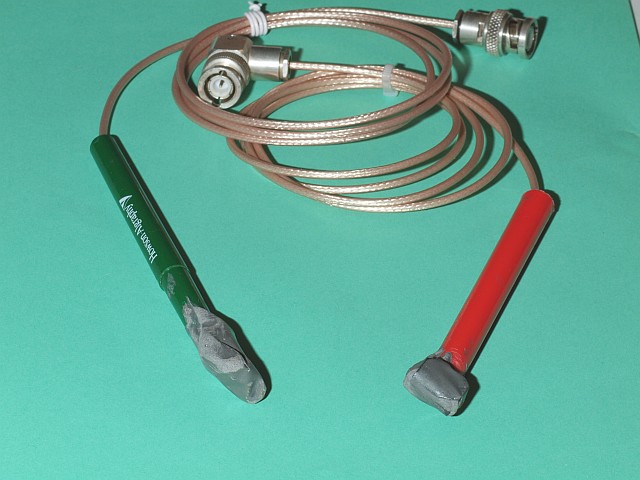
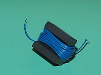
Over here some info how to build RF-sniffer probes and RF current measuring clamps. This part is not finished yet. Wait for more to come!! Because the resulting Z of a sniffer wound on ferrite is frequency dependant (I expect a 1 to 10 freq. range as practical), you need more than one sniffer for a large frequency range. To test it I made two small versions, one on half a pignose with airgap and 10 windings, the other on half a 4A11 14 mm toroid with only 5 windings. Both are "terminated" with 10 ohms, and series connected with 39 ohm to connect it to 50 ohm coax. Ferrite cutting is done with a miniature grinding wheel. Further some current clamps, one version with more signal output, it has 10 windings directly to a 50 ohms terminator, but it has a smaller frequency range. And a second version with 6 single windings in parallel, terminated with 5 ohms and series 47 ohm to coax. Lower output, buth higher frequency range. And some bigger pickup-sniffers. One version is simply a wound coax loop, terminated with 51 ohms in series on the short-circuit point. This one has a hughe frequency and pickup range, large signal is picked up within 1 - 2 meters range, also from cables in the ground. Wound on 70 mm wastewater pipe with RG174 - after glueing the pipe is removed. It has 16 windings, it is made in such a way (for relative voltage measurements...) that the total square is 1/16 sq. meter ( 25 x 25 cm square equivalent). Because it is a coax loop it is better screened to electrical fields than a "normal" pickup coil. The following in RED is withdrawn For more precise cable identification on very low frequencies ( from 10 - 20 kHz and up) a second "big" sniffer is made on half a clamp. The inductance with 30 windings was OK to comply at the design commands. It is about 80 - 90 uH and terminated with 10 ohms, connected to 50 ohms with a 39 ohm series R. Step along and click the pictures to have an idea how I made them |
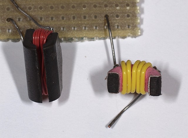 Here it starts with, a modified pignose and a 14 mm toroid. Half a pignose and with an air-gap, the toroid is simply cut in halves. |
 Damped with 10 ohm, and a 39 ohm series R to 50 ohm coax. Fixed in place on a piece of PCB. |
 And here it is stabilised with 2-comp. resin, and an old felttip pen. The ex-pen forms a luxury handgrip! |
||
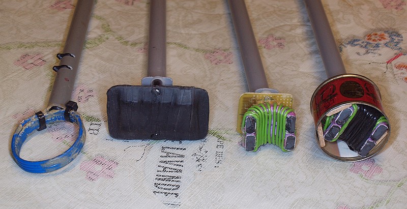
A few sniffer variations together. The RG174 loop with 4 windings. Screened and open 2 halves 4C65. And the big sniffer The basic circuit diagram or 10 Ohm parallel and 39 in series |
 The high outputvoltage current clamp and high frequency version (right). All the green windings are in parallel. |
 The new big sniffer |
||
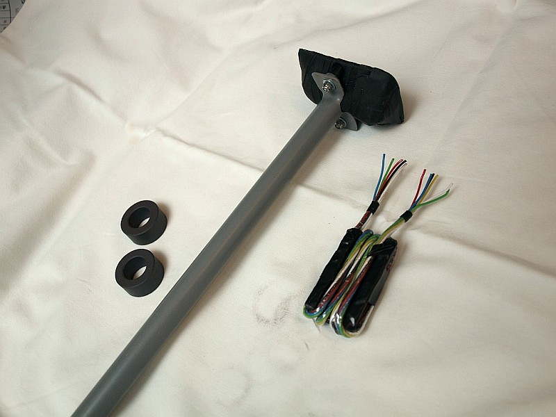
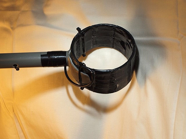 The big 70 mm RG174 coax-loop sniffer mounted on a 16 mm PVC "stick" pipe. |
 Example of a wound EMC-clamp halve with 30 windings. An earlier big sniffer. This method is rejected! Too lossy and too high Z. |
 And here the new big sniffer clamp on a 16 mm PVC pipe, isolated and protected with self-vulcanizing tape. |
|
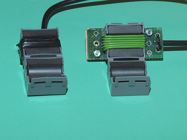
Here some theoretical considerations for a second improved BIG sniffer clamp with a hughe ferrite core. The big sniffer in the story above (in RED) with halve a standard ferrite clamp didn't work the way it was meant..... It was NOT OK!! The usable frequency range was far too low. Above 1 MHz was a problem. The used ferrite pickup unit is the middle picture above, wound with blue wire. First. The crossover point where the signal will drop off is at the frequency where the Zcoil will become a lot larger than the terminating Z = 50 ohm. To be exact: 50 ohm is in series with the windings and at the end of the cable is also a 50 ohm terminator. So crossover is at the point where the Zcoil will be a lot larger than 50 - 100 ohm. This means L should not be higher than about 1.5 uH for use up to 10 MHz. Second. The type of ferrite should NOT be of the absorbtion MnZn type (the first clamp halve was....) , but low-loss NiZn. There is lot of "airway", so always a low AL. A few windings are still possible before Lmax is reached. I've choosen a cheap "4C6" lookalike dump toroid, presumably from TDK. It is a clone for the well-known FT114-61. Two of them are cut in halves, 4 halves are glued together to form a new big lossless "halve clamp". After calculation of the AL, it is between 50 - 100, NO MORE than 4 windings are needed. To overcome negative effects of the skin effect, a litze type of wire was choosen, 6 wires in parallel. The cores are taped in plastic and 4 windings over them in series with a 50 ohms ( 2x 100 //) resistor. The back is screened a bit from electric fields to reduce pickup of shortwave (HF) signals. How it works?? Perfect!. Also 20 - 50 MHz is well picked up and seen on the spectrum analyser. In the picture above right you see the new big sniffer, you also see some original toroids and a ready wound "half-clamp" version with 4 windings with 6 mounting-wire (Litze) strains on the 4 halves. They form 1 set of 4 windings. |
 The making of the new big sniffer clamp: Two original 28 mm toroids and two cut in four halves. |
 The making of the new big sniffer clamp: The 4 halves wound with N=4 and mounted in a PCB frame. Already protected with a layer of tape. |
 The making of the new big sniffer clamp: Now also the back is seen, with a little electric field screening overthere to avoid pickup of too much shortwave HF. |
SIMPLE WIDEBAND EMC CONVERTER
|
This design is an EMC up-converter for use with the above probes (and a lot more Rx huntingloop-devices) and a portable Sony allwave receiver. The converter is comparable with other wideband converter designs, but with a few differences. Here the circuit NE612 is used with excellent results. The same circuit with a SO42P was disappointing. Lower mixing gain and too sensitive for overload. The input is ONLY usable if it is 50 ohms and wideband. And NO High-Z input!! And it should be usable from about 10 kHz. The upper input-limit is just below the medium wave band, lets say 500 kHz. Lots of interference is to be expected on medium wave if it is passed through without filtering, so this MW is suppressed. Also because most portable radio's are perfectly usable on MW as a detector! So the Rx-range becomes 10 kHz to 500 kHz. There is no interference or cross modulation from longwave megawatt transmitters (and small Rx-pickup devices or tuned hunting loops.......) The output frequency is chosen as high as practical for a standard Sony receiver. The 50 ohm load in combination with the tuned output frequency should be such that no additional manual tuning is needed. Some drop is allowed. Chosen is an available 24 MHz mixing crystal, so the output becomes 24010 to 24500 kHz. If you connect 12V directly to the BNC in- or output, they are "smoked out". If you won't take that risk add extra capacitors. For as low as 10 kHz the input needs at least 1 uF (Z= 16 Ohm), preferably use 2.2 to 4.7 uF (Z= 7 to 3.5 Ohm) !! The output will accept 2.2 to 10 nF ( Z = 3 to 0.6 Ohm). |
|
Here is the original DUTCH version PDF. Now a translated English version is also available. |
 Click to enlarge the picture |
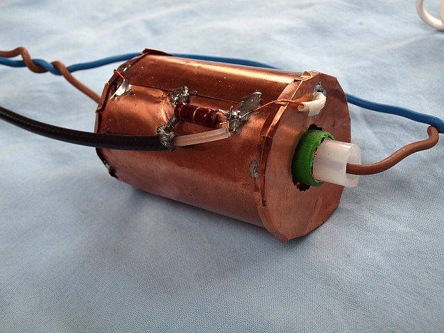
Screened mains current-transformer to accurately measure (very) low power devices.
|
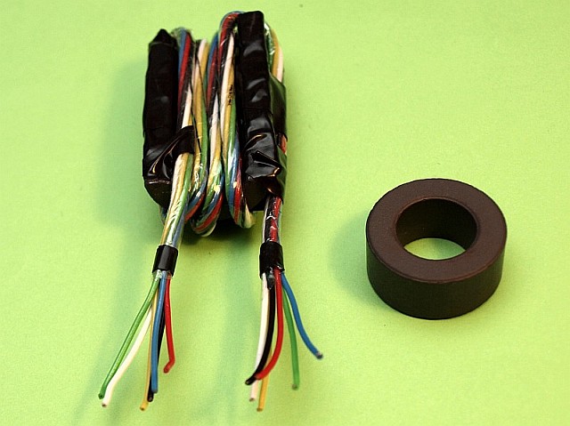
For devices like adapters and LED lamps. A current-transformer slightly different than usual.
in short: Made with 4 glued MnZn high AL ferrite toroids. The inductance should be such, that the secundairy terminating impedance (1 Ohm) is equal or less than 1% of the total Z. So secundairy Z for a 1:100 transformer should be 100 Ohm on mains frequency (= 50 Hz). Further more it should not act as a too high absorber up to frequencies to 100 kHz, so not too high in ferrite loss curve. This transformer consists of four 3E25 ferrite cores of 36 mm stacked together (TN36/23/15, AL per core approximately 7400, these Ferroxcube {ex-Philips} cores were previously orange colored). Together they are provided with exactly 100 turns and terminated with a resistance of 1 or 10 Ω. 1 Ω gives a better frequency characteristic in the low, 10 Ω gives much more output. Used with an amplifier 1 Ω is the correct choice. Check of the design criteria: L = N2 x AL x 10-9 Henry and Z = 2 x pi x f x L This makes the 50 Hz Z with 100 turns and 4 toroids: 2 x pi x f x N2 x (AL x 4) x 10-9 = 2 x 3.14 x 50 x 100 x 100 x (7390 x 4) x 10-9 = 92.87 Ω This is very near the design criteria of 100 Ω. So 4 toroids will do! And three won't be OK. UNDERSTAND this well: a total inductance AL of 30000 is needed to comply! This transformer module is fully electrically shielded to prevent long-wave DX and other EMC interference and noise ingress. Inside the ring cores is a small piece of Bamboo-3 CAI-distribution coax as screen, whose thick middle conductor is replaced with standard insulated mains installation wire of 2.5 mm2. On the outside, 3 to 4 mm plastic foam and a sheet of copper foil (or bronze, or from a tin can) over it, which is connected to the Bamboo-3 shield only on one side. Do not make a short circuit winding. On the sides, some "rounds" of copper foil may come for a neat screening. See pictures. Eventually, an OP27 (or even much better an OP37 or Philips/Signetics NE5534 or LT1037 from Linear Technology) low noise microphone opamp is used as an amplifier (thus no longer passive) with a gain of one hundred times. With the recommended 1 Ω termination, amplifier output is 1 V per 1 A (pay attention = 2x 1.414 x 1V = 2.828 Vtt for a 1Veff sinewave). Using the maximum OpAmp power supply voltage (+ and -15 V for the OPx7, instead of only + and -5 V for a current feedback amp) and 5 Aeff measuring current which gives almost 15 Vtt as possible output voltage. Although considering the field strength Bmax, 5A is already on the high side. 1 Ampere mains power already gives about 100 milliTesla. One should rather not exceed 350 mT. I have tested it to clipping in the opamp, that is about 8 Ampere mains current, without any ferrite saturation problem. The mentioned OPAMPS have such high GBW product and slew-rate properties that no problems are expected with undistorted amplification of low levels of high-frequency parts up to 100 kHz. So no triangle distortion. Here is a polished version of the draft sketch of the circuit diagram. For a known toroid AL value, we can use this simple formula (I designed, see link further down): Bmax = (N x AL x I x 1.414) / Ae Bmax in milliTesla, I in RMS (eff.) Amps, Ae in square mm. N is the number of turns of the saturating current. AL the toroid's standard inductance value. 1.414 is the factor from sine RMS/eff to 1/2 top current value. Here a scan of a draft calculation sheet in PDF, the search for the easy Bmax formula. Two different ways to calculate the Bmax from the AL and I. The intention was (as a kind of proof...) exactly the same end result, I succeeded.... Update (more proof my formula is OK!): On the site of Prof. Dr.-Ing. Heinz Schmidt-Walter I found a few pages of one of his study lectures in which he derives the same formula. Almost the same method as one of my two described methods above. Only a bit more complex and a bit more difficult. The end result is the same! Compared to the active Hantec CC-65 the results with low current (adapters and LED lamps) are much better: the same image on the oscilloscope, but no longer provided with a solid noise smear, it is so clean! Nominal mains current: 0 - 3 Amps. Peak use up to 5 Amps. Opamp clipping at 8 Amps. Step along and click the pictures to have an idea how I made them |
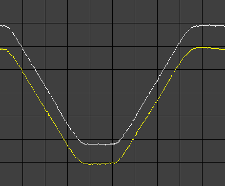
 Why I made it? Some very low current LED lamps under test. lamp5 = "glowing wire" type lamp1 = TL energy saving lamp How distorted is the mains current? What about EMC problems? |
 Why I made it? The noisy Hantek image and a noisefree track (top). Noisefree is with my new current module, made with 4 ferrite toroids and screened. It is lamp 2 on the right. |
 Why I made it? A scope capture image. This is a TL energy saving lamp. Lamp 1, most right on the lamp image. Due to the higher current the Hantek is not so noisy anymore. |
||
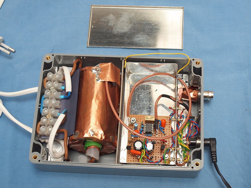
 The making of a screened current transformer: How to easy wind 100 windings on the 4 toroids that form the ferrite "sleeve". |
 The making of a screened current transformer: Here the 100 windings are finished. |
 The making of a screened current transformer: And here it is completely screened. Ready to connect to the scope or a buffer Amp. |
|
Here the screened current transformer is finished and mounted in a box. The thin metal amplifier box will also be closed. Nominal mains measuring current: 0 to 3 Amps. Peak use up to 5 Amps. The amplifier output is 1 V per 1 A, it has a higher Z output and should NOT be terminated. Pay attention, the "1 V" = 2x 1.414 x 1V = 2.828 Vtt for a 1Veff sinewave. And the 5 Ampeff measuring current gives almost 15 Vtt as possible output voltage. All very, very clean. Here is the old draft sketch of the buffer Amp in a PDF. Here is the new polished sketch of the buffer Amp in a PDF. And here is an example of the front I made in a PDF. A part of the above has been published in the monthly Dutch magazine Electron of the Veron, a few pages in a PDF. Also some of the current measuring tools information further down is included. If you do more testing of small devices (up to 4500 Watts) you should also buy the standard power HOPI HP9800 testbox via AliExpress, see picture. And also see this search link. If you do power tests smaller than 500 Watts you better buy a (more expensive) non standard version under the name AnTai ATX 9801. Search link. I ordered this one too at this shop. |
 Click to enlarge the picture 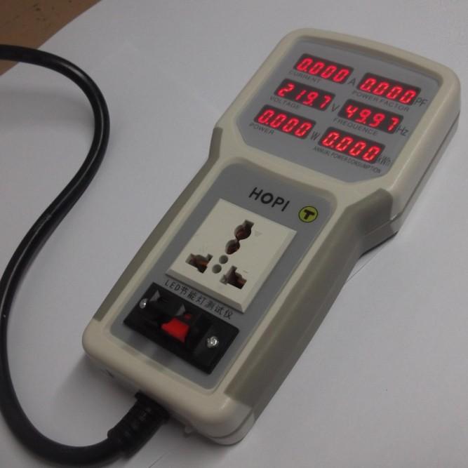 Click The HOPI test box |
|
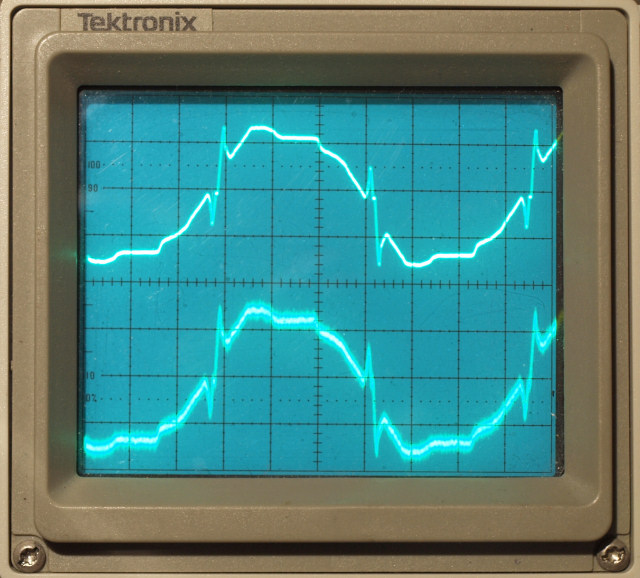
Very strange measuring results that lead to the development of a sinewave cleaner / filter.
Look at the three scope capture measuring pictures below. They are all three taken from the same capacitor current limited LED lamp. First is at the middle of the night, in complete darkness. Second is taken during bright daylight, a lot of moving noise is visible. Third is with the use of a sinewave restore filter that removes ALL mains pollution and also removes the flat roof and restores the sinewave. This filter is basically a 300 Hz low pass filter and is explaned below. Use with extra care!!! The filter gives a very clean, but unstable mains voltage, adjust/correct the voltage with a Variac in front of it! Test setup info: LED lamp4 is about 2.6 W, it draws about 50 mA eff. (RMS) current, both measured with the above HOPI instrument. Scope scale is 50mV/division. Used Ferrite block transformer = 1V/1A, so 50 mV = 50 mAmps. You see a single peak of about 75 mA, as expected (Utop = Ueff x 1.414). For the Hantek the slim 10x loop is used. The measured 20 kHz sinewave is about 20 to 50 mVtt. This value is dependant of the used series capacitor in the LED lamp, other LED lamps may give other 20 kHz values. A "glowing bulb" will give nothing at all. On my Wandel and Goltermann SPM-30 connected to the ferrite block module I measure signals between 20.600 and 20.700 kHz, with a power peak about 20.688 kHz. |
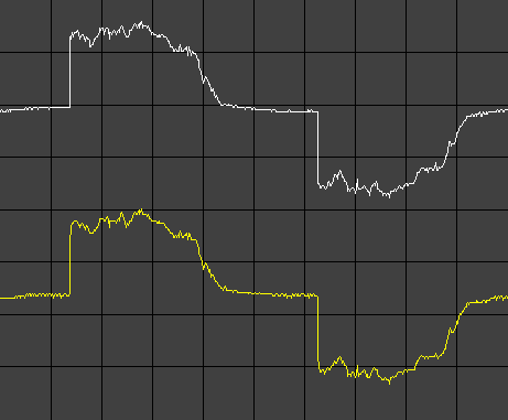 A strange LED LAMP 4 curve: This capture image is taken at night. It looks absolutely normal. But, it is NOT. Top is ferrite module, bottom is Hantek CC-65. Hantek with the slim 10x loop, see further down. |
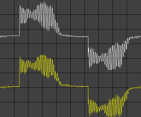 A strange LED LAMP 4 curve: This capture image is taken in full sunshine. A very strong 20.6 kHz signal is visible. The 50 Hz current limiting capacitor is 400 times less in Z on 20 kHz. It sucks solar power converter EMC from the mains! |
 A strange LED LAMP 4 curve: Mains is LC-filtered with 0.5H + 1uF It forms a 300 Hz low-pass. This is with the sinewave restore filter. It is descibed below. sine = filtered mains, current has +90deg phase shift |
|
Current measure experiences with LED lights.
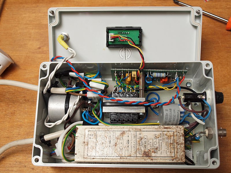
After a large number of tests the recorded current curve of LED lamps, with internally a large series capacitor, appears to be highly dependent on the harmonics and other (EMC) mains contamination! The Z of this Cap becomes increasingly LOWER with going higher of the interfering frequencies! You could simply say that these types of LED-lamps "suck" the EMC from the mains. Can they therefore rather fail earlier? See above pictures. The measured current curve actually gives an indication of the amount of mains pollution and does not actually provide the right current information as it would be with a "flat ironed" sinewave. During the day, a very large proportion of residual EMC of solar panel converters is visible, multiple signal sources of approximately 20 kHz "interfere" to a dancing wave. After these extraordinairy experiences with different current curves of the same LED-lamp with a series C in the supply (day / night / interference with other devices), I found it necessary to make a sort of test filter that ALL EMC and low LF would remove, leaving a pure sine wave. The practical use of it is limited, but, you can keep yourself busy ..... Only then would the "ideal" current curve of such a lamp be measured. No real world curve, but what would the LED current curve be without all LF junk on the mains and without a sine with a flat roof. The making of a reliable filter turned out to be very tough ...... Disapproved: 1) Two back-to-back connected transformers (230V ==> 24V / 3A ==> 230V) with a 10uF washing machine capacitor in parallel on the 24V AC. Or even a multi-stage filter in between. Disapproved, the transformer gives strong LF harmonics by magnetic deformation. 2) A very heavy (standard) LC mains filter with 10 to 20 mH inductors and some capacitors of 0.5 - 1 uF. The highlevel solar panel LF and HF is gone, but the low LF harmonics are now dominant. 3) A Philips ferroresonant (dissipative) magnetic stabilizer. Here too, the LF interference is even gone, but now there is a very strong 8th harmonic (400Hz) through the sine. This also spoils the ideal LED lamp curve. 4) A 7-9-11-13 W TL inductor (2.5 Henry!), with 5 or 10uF, could form an ideal lowpass barrier. Provides approximately a 50 Hz low pass filter, like after a transmitter power stage. Indeed, the sine is finally ideal, but after 1 minute it started to smell overheated by serial resonance effects due to a too large excessive LC (resonance) current. Also: it's easy to get more than 300V output! Abuse of the capacitive TL ballast version (L + proposed C) is asking for difficulties. ==== Option 4 could work with other component values. A heavier TL ballast for 40W TL is also available, the self-induction is about 500 mH = 0.5 Henry in this case. "Manufacturing" current is 0.44 A. If the f-res is set slightly higher than 50 Hz and an additional damper glowing wire ballast bulb is connected it could work, then no strong resonance effects. Set maximum ballast 60 - 80 W. Set resistive load approximately 750 Ohm for this LC filter. With Elsie I get with this 0.5 H (low Q) and a chosen 1 uF a 300 Hz lowpass. A heavy duty C of 1 uF (working voltage 400 V AC) in a metal can enclosure was available. This seems to work fine, although the actual voltage is very dependent on the load. A variac is always required to set the correct and safe mains voltage. A built-in mini AC voltmeter would also be handy. A double-insulated safe mains-reference output (for phase difference I and U measurements) would also be useful and less dangerous. Because it is an a-symmetrical filter, it is convenient that the choking impedance is NOT in zero line but in the phase. To indicate the correct L-N connection, a voltage screwdriver neon indicator lamp, provided with 2x additional current reducing Rs (devided over both AC wires one) would be useful. Added 2x a 100 kOhm resistor. A 0.5 to 0.8 mA temporary leak must be permissible. Normally, after rotating the mains plug, this lamp is OFF. (A 3mm high brightness LED with clamp diode and 2x 150 kOhm will also work, with only 0.5 mA) A 150 Hz series resonance (3rd harmonic suction) circuit in parallel to the output may even improve the sinus wave slightly, but provides a greater mains voltage resonant rise and thus even higher instability of the filter. Dangerous unloaded rise now to 350V!!! I use a 0.3 Henry (125W) HPL choke (Ri = 6 Ohm) and a set of smaller X2 mains capacitors (2x 1uF and 3x 0.47uF) up to about 3.5 uF to tune the circuit on 150 Hz. Be carefull with the loaded Voltage setting! Variac on 150V is already OK. The 150 Hz tuning and alignment test can be done in series with a 470 Ohm resistor and a LF generator. After the R you should get a serious dip at 150 Hz. Setting f a little lower than 150 seems better. Adjust the capacitors if needed, because the inductance may drop slightly due to the 50 and 150Hz mains current. Smaller sized lamp inductors (0.5H for a 40 W TL) have such a high internal resistance (30 Ohm) that they give no serious dip. It has become a bit of a weird case, but again a test box added to the toolbox..... |
|
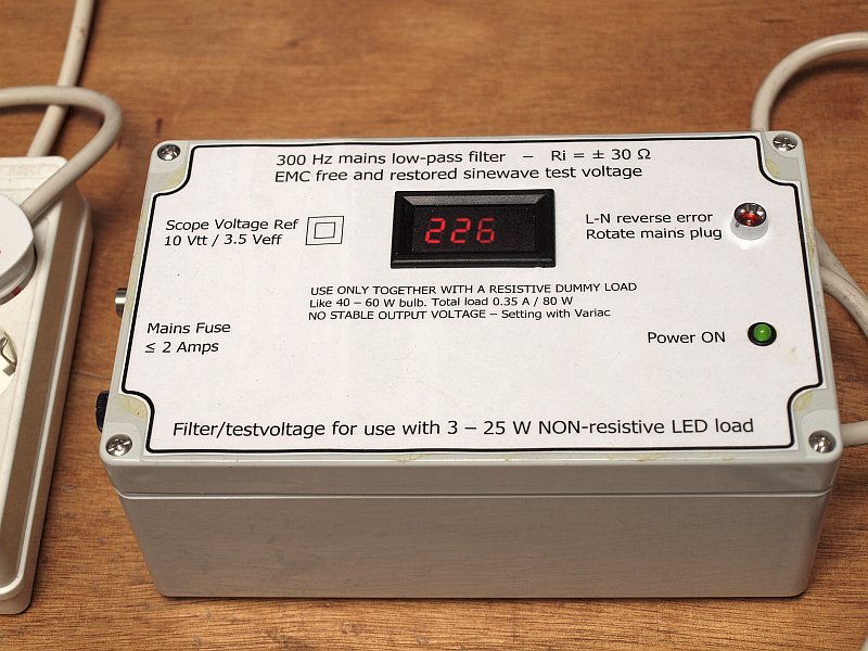
Here is the polished draft sketch of the 300 Hz filter in a PDF.
And here is an example of the front I made in a PDF. |
 Click to enlarge the picture |
 Click to enlarge the picture |
|
Some info about the 150 Hz suction filter that could be used with the above 300 Hz unit.
|
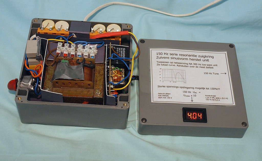
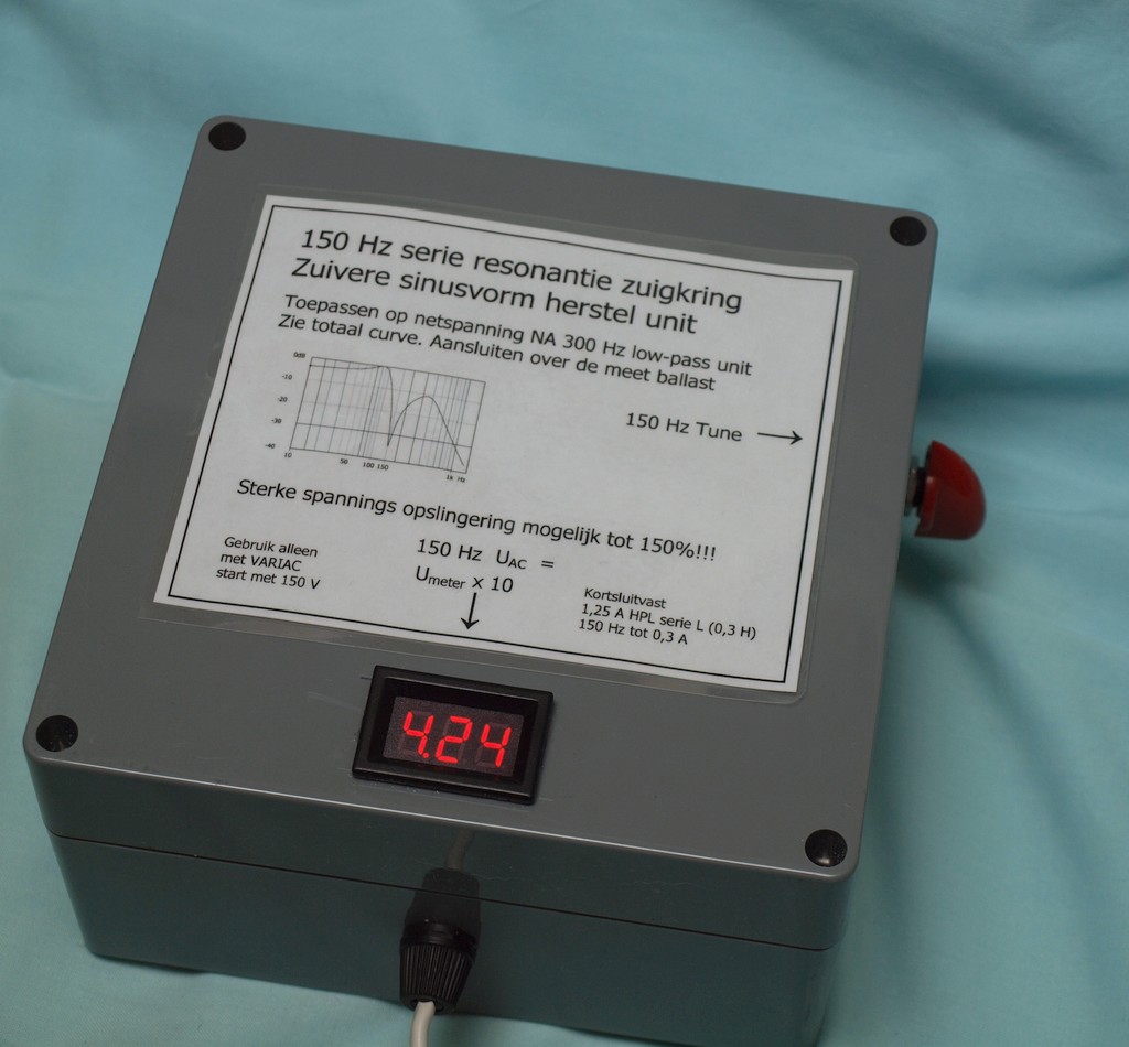 The box is operational |
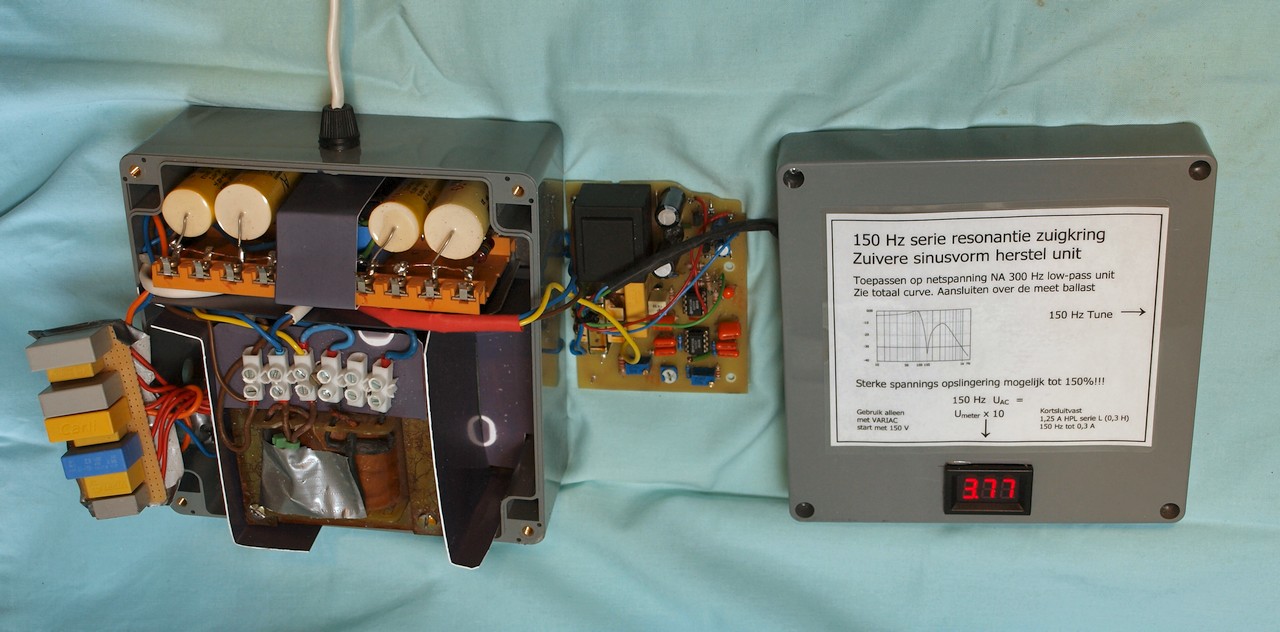 An "exploded" inside view Left C-bank is to tune 150Hz Right the filter PCB with meter driver Very "draft" schematic And the PCB design |
 A 2nd inside view And here is an example of the front I made in a PDF. UK and NL version |
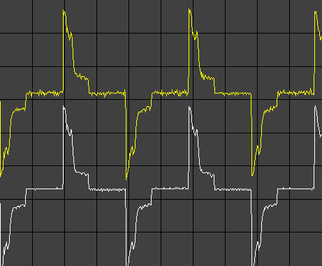
Compare test of the YHDC current transformer, SCT013 10A/1V, with build-in terminator In several test-boxes I used this YHDC transformer. It is handy, small and cheap. After designing and calculating my own hughe screened current-transformer (see above) I found out some possible drawbacks. I had to make my big toroid transformer TWICE, due to a too low inductance first! Below I compare some transformer versions to find out how other manufacturers cope with those low inductance problems. Click here for the YHDC datasheet. It is a crippled JPG file. Meanwhile, I found a real PDF The biggest problem when using ferrites is a lack of needed inductance, this limits the low frequency part. If there are "squarewave" parts in the current curve those parts have the tendency to sag. Or jump up or down from the scope baseline. If pure laminated steel is used, this limits the high frequency part. Look at four scope capture measuring pictures below. They are taken from 4 different current transformers in a mains-line with a standard glowing bulb. So only displaying an almost linear relation with the mains sinewave with a "flat roof". As reference is used the Hantek, because it works with a hall element and has no problem with the low inductance problem. It standard works from DC!!! The Hantek curve is in all four the WHITE curve with a FLAT bottom or roof. Taken with the 10x tiny loop. The last picture is my own screened toroid transformer version, this is an AC only device (with buffer Amp), but made with the calculated inductance as it should be. It is a 1 : 100 device, the ferrite AL should be 30000. Only than Z and terminator comply with the design-rule that the terminator-R is only 1% of the inductance Z at 50 Hz. You can see why! Disadvantage: it becomes very hughe......., but the results are clear. YHDC should change the construction. But most of the time the YHDC clamp is still usable. |
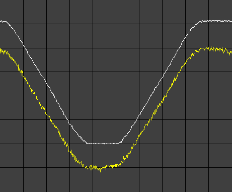 yellow curve = ABB module with a build-in terminator Too open construction, much noise pickup |
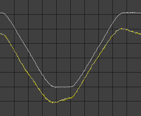 yellow curve = Fluke module with a 10 Ohm terminator This is the max. allowed and appears too high |
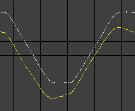 yellow curve = YHDC The combination "inductance" and "terminator" is not ideal. One of them is WRONG! |
 yellow curve = PE1ABR ferrite block As you can see: almost ideal As flat as possible for an AC clamp. The terminator =< 1% of Z |
|
Earlier current measuring tools and add-ons, very usable for the Hantec CC-65 and others.
The 10x current "amplifier" without electronics Here are some hints to make up an 1 to 10 current aid with plug and counter plug for measuring low current devices. It is intended to connect in series and increase low currents by a factor of ten for an ampere/current clamp module. Of course, no currents are externally amplified; It's just a bunch of ten windings that go together through the amp clamp. The clamp beak must be large enough, or use a slightly thinner (transformer enameled) wire, this is needed for the Hantek CC-65. A single winding is also available, so we can choose between ×1 and ×10 during the measurement. In the pictures you can instantly see what I mean. |
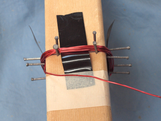 The making of a thin 10x loop for the Hantek CC-65: Some nails makeup the temporary coil form on a wood pole. This loop is made with thinner enameled transformer wire |
 The making of a thin 10x loop for the Hantek CC-65: Testing of an almost finished 10x loop. Not protected yet with a layer of tape. |
 The making of a thin 10x loop for the Hantek CC-65: Here the loop is finished. This version fits nicely in the Hantek CC-65. The 1x loop is protected with a teflon tube. |
||
 The making of a 100x !!! loop: As a test (for very low adapter currents) a 100x loop was also made. Due to its higher inductance (750 uH) it picked up even more EMC. |
 The making of a 10x loop: This is the first 10x loop It fits only in clamps with a wider beak It is made with wire from standard mains cord. |
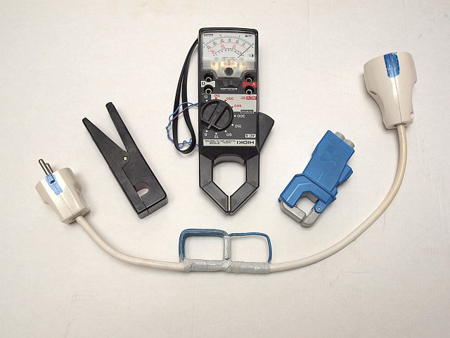 The making of a 10x loop: All sitting together The first 10x loop and the first current clamps. For very low LED lamp currents and the new Hantek CC-65 it needed an update. Black clamp = Fluke, my HIOKI analog clamp and blue = ABB clamp. |
||
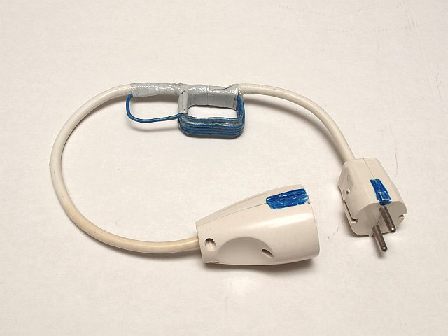
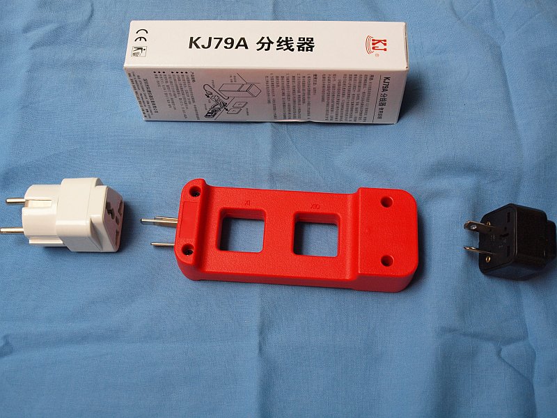 A shitty 10x loop from China The KJ79A from AliExpress is cheap, and has a nice enclosure, but shitty Australian connectors. Nothing else was available. Only with some trouble you can find suitable adapter connectors. |
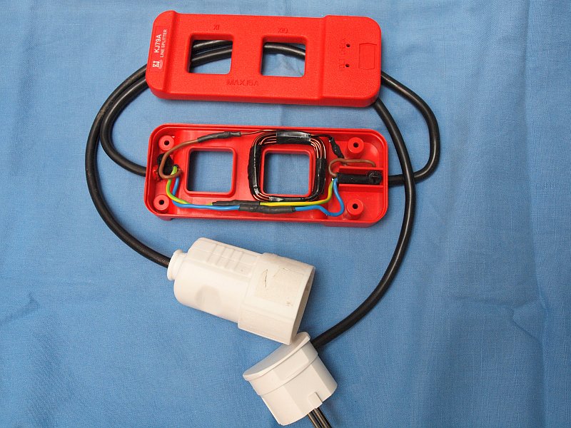 An improved shitty 10x loop from China And here the connector problem is solved, I rebuild the connectors! Very stable. LOOK WELL: there is something very special. The coil has only 9 windings, but on one side mains return (blue) forms the 10th, on the other side start and finish overlap, so also 10. |
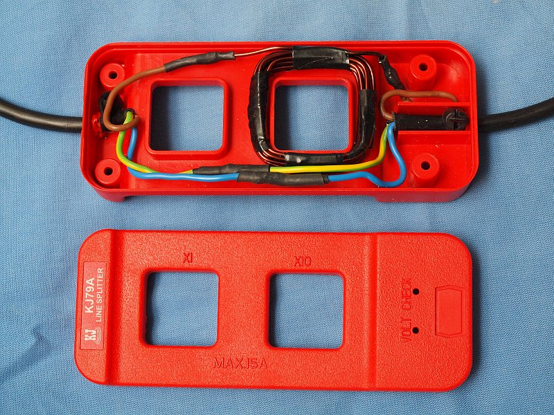 An improved shitty 10x loop from China And here a little bit more zoomed in. It works very well and it looks nice! BUT: the Hantek CC-65 does NOT fit! We still need the enameled wire loop. Last KJ79A ones available link Or replacement more simple UT-LS10A |
|
And all the above started with the making of a safe test box for equipment directly powered from mains.
The first version of this testbox was published in the Dutch magazine Electron march 2017 (VERON) and was made by PA0JBB. I also wanted to have such a testbox, but with some extra's. A heavy on-off switch and dual fused. Bright Power available indicator BEFORE the switch is closed. It is made with a high power 3mm white LED directly on mains, but with 2x a 150 KOhm in series and a clamp diode over the LED. It only draws 0.5 mA! A small screened current transformer build-in! A L-N error indicator if the mains plug is connected the wrong way. It is made with a screwdriver neon bulb with additional 2x a 100K resistor. If lit it only draws less than 0.8 mA to ground, this leak is permissable. Normally the neon lamp is OFF. After some experience with 3mm white high power LED's: they can be used too on 0.5 mA. See Power LED above. In the right top corner in the middle image, where there is some space left, a Voltage / Current / Power meter module is added later on the right side under the outlet wall socket, with its own current transformer. Look at Ali over Here. |
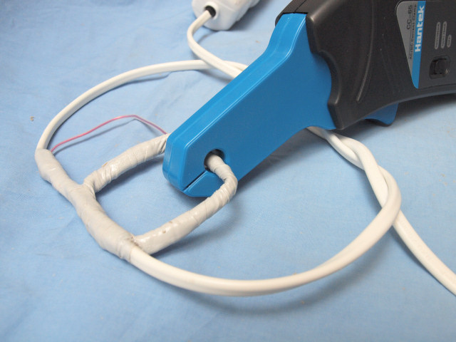
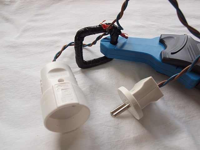
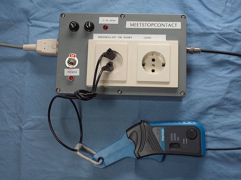 The outside of the box connected is a special 10x loop |
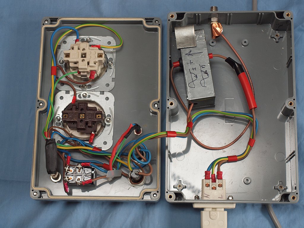 This is the inside of the box Added is a.o. a screened YHDC module The wall sockets metal mounting plates are on the top side on the lid. You see extra underneath plates to better clamp the wall sockets on the plastic box lid. |
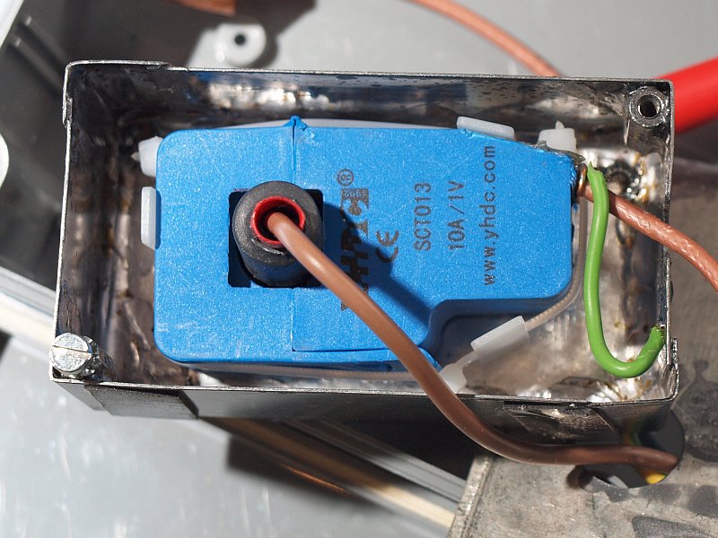 Also the YHDC module is screened It gives a much clearer picture on the scope. The compartment should be closed with a metal lid. |
LISN 1600
|
Obviously I also use a professional LISN (Line Impedance Stabilization Network). It has become the Thurlby Thandar LISN 1600 with German Euro connector. A version with the Dutch COMTEST label on it Here is the leaflet with all data in a PDF, a version without mutilations. And here the full instruction manual, a sharp version. But with a stupid error, see next item. And a personal document with some text errors I found and a useful modification |

Click for a larger picture |
A beautiful mains plug with a switch, but unfortunately very poorly designed.
|
After some bad experience with local bought mains plugs with an on/off switch I tried some from AliExpress. They were NOT as fine as I expected.......... Advertised as either 10, or 16A - 250V, but really ONLY usable up to max. 1 Amp. E.g. an outdoor LED lamp. There is NO separate (rivet) contact material used, it is 2 bumps on the steel movable tabs. And the counter tabs have a brass bulge. Larger currents than 1 Amp will create too much heat and there is a great chance of the plastic housing melting away! I found some web images with damage of comparable plugs. Furthermore, the earth contact bridging strip (between external earth lugs and wire-screw fastening lug) is glued with PLASTIC, NOT connected with a metal rivet. The earth contact connection is therefore NOT guaranteed OK, it is simply "loose". There is also a CE mark to give you a good laugh! |
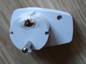 Not the same as I bought but comparable melting |
 A lot of them for low cost |
 There is NO real contact material used, just a few center punch bumbs |
 Also the earth strip has NO connection rived, it is glued in place with plastic! |
NO Navtex Rx due to an interfering switch adapter.
|
Currently there are beautiful cheap 5 or 8 port ethernet (UTP) 10/100/1000 Mbps switch boxes for sale at many Chinese AliExpress shops. Included is a small 5V switching adapter, which is also sold as a 5V USB charger, seen the printed markings on the PCB. Equipped with a modern control chip, the MD1800 or MD1801. From the datasheet: low cost and minimal component count due to primary sensing feedback, so without a TL431 and opto control. Also good characteristics without EMC components. Well, there is something to be said about the latter .....: bullocks. Within 20 meters, reception is no longer possible on the Navtex frequencies between +/- 400 and 520 kHz. (with a magnetic loop antenna outside!) Because of a huge S9+20 grunt. Also within a distance of 50 to 20 meters serious DX nuisance. Adding a 230V common mode filter test box (2x 1 mH common mode, 2x 100 nF) gives a reduction from S9+20 to S9. So definitely NOT gone yet, apparently the 5V cable (and the switch, and the UTP cables) is/are also radiating. So I put the ax in it to see why. As expected, it contains NO (anti-) EMC components, even a reserved space for a Y2 - 470 pF is empty. By removing and mounting the mini PCB in a small Hammond box (1591M) (Conrad 534347) with appropriate extra common mode coils at the INput, as well as the OUTput, and also adding suppression capacitors, the malfunction is really 100% resolved. See pictures. |
 A picture from one of the providers |
 Extra needed EMC components Yellow core = 25mm 3E5, very high lossy AL with N=2x 15 red/blue. Orange = FX1000, 2 stacked, also very high lossy AL with N=2x 20 thin teflon wire |
 After the coils an extra C is added, directly over the in- and output Mains = 47 nF - X2 +5V = 47 or 100 nF 100V L - 3E5 = +/- 3.6 mH L - FX1000 = +/- 2.3 mH |
 On board added: mains 100nF X2, after 10 Ohm R Trace to R is cut, Cap is over AC bridge terminals +5V = 47 or 100nF 100V. The deleted 470pF Y2 is also added |
|
More peculiar info.....
Another (Ali) +5V power switch supply unit, delivered with a large USB hub, was fitted with a screw. No glue. Although no interference detected yet, the screw was an invitation to give the inside a look. NO IC, but a single small transistor (MJE13001 = 13001 S8D) did all the work. Here also a primary sensing feedback circuit. See pencil drawing. On mains only a single diode, not a bridge. And also not a single anti EMC component. Safe distance between mains and output PCB tracks was way too small. BUT: there still was an opto coupler soldered on the PCB! And it was only connected to primary ground, NO actual use in the circuit, so a completely useless dummy component. Very strange. I removed it to make place for a standard Y-cap of 470 pF between mains and output. |
A nice professional Diode / LED / Zener test box.
|
The first version of a diode testbox I saw on the internet was this Dutch
Circuits-Online page
I wanted a much more expanded version, so I designed my own, starting with the above currentsource circuit. My improvements: The DVM needed 2 extra digits and through this NO range switch is needed up to 30.000 Volts. DVM for a very low price available in China and works from zero to 33.000 Volts. The input impedance is NOT very high (350 kOhm) but it will do the job without a buffer. At the lowest current ranges, the maximum open Voltage as a result will drop a few Volts. I added a much larger current range, if rather high, protected with a safety push switch. The range switch is "open" before "close", so when rotating the current range switch the emitter is open between steps. I made it such that the lowest range functions always as a bypass. This has been taken into account in the resistor values in the subsequent ranges. Because a higher voltage is available also a brightness test is added on an old SCSI connector. This is, due to the higher Voltage, less dependant of LED voltage drop with simple resistors, than cheaper versions with a 9 V battery. I also tried to add the "Bob Pease Pulse Test" on the same diode connection terminals, but that appeared not possible. So still added, but on an extra set of terminals. With three frequencies and three current ranges. What the heck is "Pease Pulse Test??????" See a few scanned pages in PDF from a book from the USA, and also a few from a Dutch translation. On second design thoughts: On low 230V mains distribution loads, and the chosen older 220V - 17V AC adapter, the unstabilized DC voltage may rise here to just above 40 Volts (about 40.5 to 41V), which is high above the design limits (=37V, max. 40V no damage) of the two used standard LM317T regulators. It is wise NOT to use those and to use the special higher voltage version, the LM317HVT. It can withstand 20 volts more (=57V). This is much more reliable. Available for download: All the CAD files. All the draft drawings. The front layout . And below a few pictures |
 This is the inside of the box |
 The outside of the box, with tools The brightness test on the SCSI cable. |
 Behind the SCSI cable is the resistor network board. |
Pulse - Echo generator box
|
For measuring the ideal termination of a cable or (winding) wire strain (for Guanella baluns...), you connect a pulse generator and scope to one
end and a low-ohmic termination potentiometer to the other end. Rotate the R until minimal echo bumbs ==> Now R-Potmeter = ideal termination-R. This works pretty accurate between 20 - 250 Ohms! If you also want to do a length or velosity measurement (also of an entire reel ...), you need a single very small pulse combined with an extreme long pause, otherwise you are unable to detect which echo is from which pulse. My generator box makes these small pulses in 4 different pulse/pause settings. The 4 pulse width's at the same time can give an indication of the common mode suppression frequency range. The generator consists of a single 30 MHz crystal oscillator module (old PC scrap), a very fast 74HCT4040 for lots of divide by 2 stages, and a GAL-array logic chip wherein all the pulse/pause combinations are programmed. Eight divider chains and combiners would consume an entire eurocard with standard logic, here only 1 GAL16V8 chip. The shortest pulse is made from only one 30 MHz sinewave. So comparable with half a 15 MHz pulse, due to some chip-delay it looks like half a 12.5 MHz pulse. The total pulse/pause can be compared with the T from an 85 kHz wave. There are two buffered outputs, one low-ohmic optimised for test cable connect, the other positive or negative going selectable to sync the scope. The most time consuming part in the design (above 15 years.....) was a buffer that has low output-impedances, but also as fast as possible. Too high current = SLOWER, more delay! The box that is used is a German Strapubox 2002. Conrad number = 522139 DO NOT connect the Y scope input with a T-adapter, but connect a 1/10 probe to the cable-strain connection point. And ALWAYS connect a 50 Ohm terminator at the end of the sync cable to the scope to keep the pulse "clean". |
|
Here the CAD PCB files in PDF Here the schematic in PDF Here the GAL design files in PDF Here the GAL program file Here more explanation in a PDF Hier meer uitleg in een NL PDF 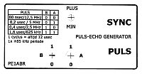 Click to get the front in PDF |
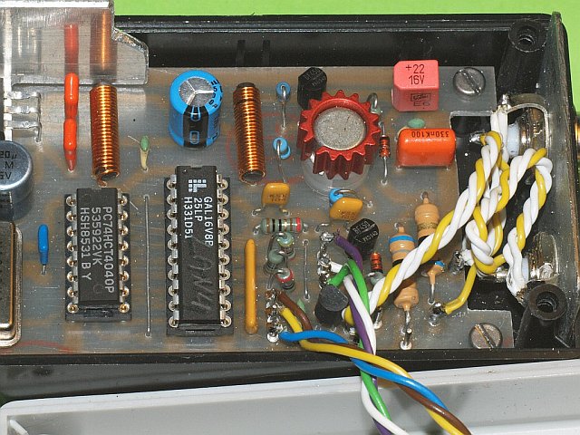
 Inside the lanpulse box.  Example adapter's modified PL-259 ==> BNC to connect all sorts of cable strains |
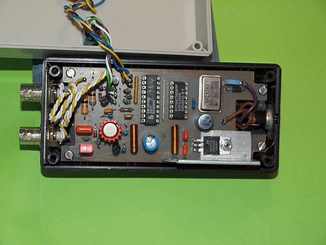
 More detailed view inside
|
Ethernet UTP measuring tools
|
Here some very simple tools that make it easy to solve all common UTP wiring errors.
To be used with only an Ohm / conductance meter with buzzer or Fluke(alike). Very simple but extremely handy if you are called to solve a problem. Make more than one of them. 1) A piece of PCB clad with the 8 wires connected to solder lugs, you connect your ohm meter with hooks to it. 2) A piece of 15 cm UTP with a connector. The 4 pairs are shorted to each other to do a connection (buzzer) test at the other end. Make more than one of it. 3) A piece of 15 cm UTP with a connector. The 4 pairs each have their own dummy terminator. Each pair has a different value to distinguish the pairs from each other. Use 100 ohm for orange, 150 for green, 220 for blue and 330 ohm for the brown pair. Make more than one of it, you can solve almost any error with it! Add some UTP/RJ45 inline couplers to your toolkit. WATCH out for misunderstanding! Double check your supplier! You only need coupler versions that connects the pins crossed, pin-1 at one side (crossover) to pen-1 at the other. They are (mostly) confusingly called STRAIGHT! Straight through connected (pin-1 to pin-8) is common called CROSSED! They are only usable for ISDN / Telephone. 4) If you want to investigate impedance imperfections with the above LAN Pulse Echo generator, you also need a 15 cm piece of UTP with a connector with the correct termination dummy R's connected. A value of 4x 110 ohm will do (or 2x 220 for each in parallel). For length measurements use left open or the "short" dummy at the other end. You also need a very short twisted pair cord with BNC (female chassis with male-male plug) at one end and crocodile clips to the other to connect the generator to the UTP pairs - You really need only to test the orange-white and the green-white pairs. Connect the very short cable with the clips to the lugs on the PCB-clad board, also connect your scope to those lugs. If you have mental problems with the a-symmetric to symmetric measuring connections add 10 windings UTP on a high AL ferrite core in the cable to the PCB-clad board. This suppresses the imbalance in the measurement setup. |
Some cable measuring results: old UTP Solid CAT5 test 18 meters: measured Z = 110 ohm, velocity = 0.676 UTP Stranded CAT5E test 48 meters: measured Z = 102 ohm, velocity = 0.696 |
 Click to enlarge the picture |
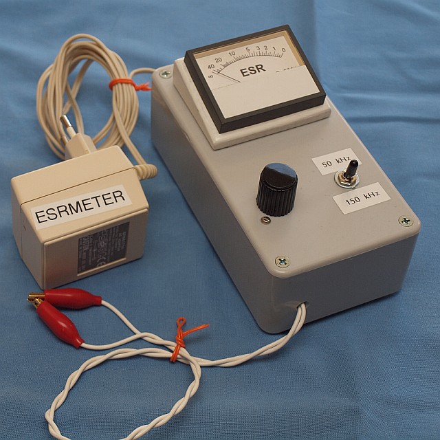
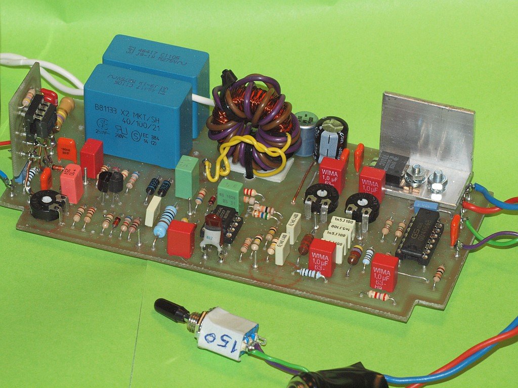
A NON-standard ESR meter
A combination design. Both 50 and 150 kHz pure sinewave measuring signal, accidentally 230 V misuse protected, extreme low-Z signal, output independant of load changes and frequency. All switch-over with a 4066 IC, 50/150 kHz switch = "cold". Add-on buffer possibility to use large 500 - 10000 uA (=10 mA) meters. Without buffer: 50 uA to max. 250 uA. Not a stripped minimalist design!! Schematic in PDF CAD PCB in PDF |
 |
 |
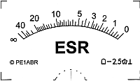 Meter scale in PDF |
|
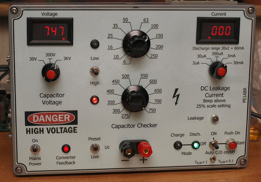
A rather complicated capacitor leakage current test box. Also to regenerate old stock electrolytes, current limitation then with the help of an extra series-R box. |
Wil je dit stukje zien in het Nederlands ?? Klik op vlag of HIER |
|
This device can be seen as a modern upgrade of (only) the leak test possibilities in an old
Heathkit IT-11 or IT-28. This new device is NOT intended to measure the value of a capacitor. Modern RLC meters (Elektor and Mastech) are 100 times more accurate than the Heathkit bridge. Therefore it has only a limited use. It was a kind of retirement project for me to stay busy! The basic circuit design is simple and comparable with the Heathkit. Only here much more extensive, slightly higher voltage, much better protection against clumsiness and therefore sensitivity to malfunctions. O.a. a fixed delay between C connected to high voltage (charging) or the same C-point to ground (discharge). All high voltage switching via high voltage reed relays. Despite the use of special 1000V reed relays , a sticky contact can give a full shortcircuit on maximum 750 V DC via the (happily) always present safety series R's. That is why there are two relay contacts in series on those tricky places. Unlike in the Heathkit, separate safety resistors have been used for both charge and discharge circuit. |
 The box is operational |
 The box in exploded view |
|
The box is equipped with 4-segment digital meters for voltage and current. (
RD Official Store via Aliexpress
). These must be modified to give fullscale 30V with only 10V input and also 3
external decimal points are added with
micro LEDs glued
on the internal display side. These meters have a much too low Rin for most applications, so they are provided with my own design MOSFET buffer in front with 1.5 Tera Ohm input! These standard meter buffer opamps, working on max. plus and minus 15V power supply, and give not more than + 10V out, hence the conversion from 30V IN to 10V. Eventually one has created a switchable voltmeter (with 3 or more ranges) with 30 Meg Ri input. Over the current shunt of the current meter falls on the lowest range at max. indication of 3.000 uA not more than 0.3V. The last segment indicates 1 NANO Ampere. It is understandable because of the extremely high Zin it becomes EMC sensitive ... (you even see the imposition of a hand). Partly for that reason, and the effort it took to suppress hum, the two measuring buffer PCB's are largely behind a tin / steel shield. There are 5 I-ranges between 3 uA and 30 mA. The highest position is normally not achieved, only with current spikes. These U / I systems can also be build as stand-alone units for other applications. |
 This is the top side of the voltage system |
 This is the bottom side of the voltage system |
 Charge / Discharge control board |
||||
 This is the top side of the current system |
 This is the bottom side of the current system |
 The High / Low voltage control board With switch-on preset low and safety switch blocking during charge mode |
||||
 The beeb and timer control board |
 Half dismanteled: the current board and Charge / Discharge controller |
 Some connect tools For stability a "dead weight" is added in the box, made from a block of cast solder. |
|
The high DC voltage, internal max. 780V !!!, is generated with 3 mini tranformers from 9 - 12V AC used backwards. Powered via an AC controller from 18V AC.
Every transformer is provided with its own rectifier and electrolyte, therefore are ordinary standard parts possible. The AC voltage regulation is of the dissipative analogue type, directly regulated in the AC low voltage with a DC circuit behind a rectifier bridge! Trick special. Because this gives the least EMC risks in the sensitive MOSFET buffers. There is also a well-functioning triac controller designed with extremely "soft flanks" through 25% unregulated current by-pass in parallel. The analog control therefore also does that. This triac arrangement is even somewhat better than the analogue version, 450 to 900V DC is neat adjustable with the same set of three transformers, but NOT applied, due to EMC risks. Also the needed space for three additional 36 mm toroids was a problem. |
 This is the Resistor divider chain soldered to the two switches All the needed metal screening is extra isolated |
 Here the completely finished unit is opened. At the very top the fan At the bottom two air intake holes On the tray with the R-divider chain and two switches, a mini fan |
 The external decimal micro LEDs glued to the display side. |
|
The voltage setting is achieved, as with the Heathkit, with an R-divider circuit, and large rotary switch. By choosing extra spacious contact distances with a limited number of connections here, I have chosen to use TWO switches. They also have to be modified a little. Is also a lot safer. See details in the diagram. Maximum current in the voltage setting R-chain is 10 mA (= 7.5 Watt!), Only a part of it can be taken without extreme voltage dropping. In Idle-Charge the current is almost zero. For the highest range of 750V there is an extra safety R-set (2x 1K5 5W in series = 3K 10W) that standard dissipates 30V away from the 780V. In case of an accident, it catches a part of the whack. This was a design flaw in the Heathkit. You could blow the rectifier tube. Wrong actions and accidents are blocked in the switching of the relay control. With the help of a flip-flop with delay and control relays with interlock accidents are prevented. Even when you shoot out with a measuring pin. This principle has been applied twice, both in the high / low voltage changeover as well as in the charge / discharge control. For use as an electrolyte regeneration unit (for old stock or new 30 years in a box) there is also a repetitive charge / discharge timer. Later, when the main cabinet already was much too full, there is also an extra external maximum current setting box added, made with a set of power R's for limiting the electrolyte current. You can then limit the maximum current to max. 5 mA (or much lower) and hopefully prevent an explosion. Or a smoking voltage divider .... The device is static and EMC "grounded" due to interference suppression, but it is NOT hard connected to ground to prevent electrocution hazard. See diagram. |
Available for download: | |
| Circuit diagrams in PDF, 13 sheets......... | |
| All the CAD files / PCB layouts in one PDF v4, an update will follow | |
| The two front layouts in one PDF | |
|
|
The two metal plates in the making for the print buffer trays in a single PDF, this is the pure black and white version PDF. Front view, the flaps must be bent down. There must also be a cover plate between the flaps on top of the PCB, the size is the same as the PCB, This cover is not on the drawing. All the material is thin steel sheet, scrap tin from old PC cabinets. |
|
|
Again the same two metal plates in the making, but now optimized in GRAY in the PDF. |
| Capacitor leakage current information sheet from the web | |
An extremely polished and edited electrolyte leakage current table from the web. This is only applicable for very old electrolyte's with much larger leakage current, so "old stock types". For older small electrolyte values in this table, the leak is up to 5 to 20x greater than in the table below for new electrolyte's. | |
My own version leakage current table, only for aluminum electrolytes. For recently manufactured Alu electrolytes and a 25 degree environment temperature: I-leak is much smaller than 0.01 x C x U, and min. 0.5 uA is permissible under the formula value. Three output versions in 1 PDF. For quality tantalum, 0.8 times this value is normal (and also 0.5 uA). For standard drop tantalum, 1.5 times the value and min. 1 uA is standard permissible. The table is therefore only a general guide value. | |
The above leakage current table, is "programmed" in simple minds DOS Basic and exported to CSV. Nice and quick and easier than doing everything on a calculator. Then some CSV edit from UK decimal point to NL decimal comma for Dutch Excel import and adjust some rounding errors. I had forgotten the INT (1000 X + .5) / 1000. This looks better without unnecessary decimal zeros. This way you can see how I did this. A number of files in a Zipper file | |
| |
|
Diagram PCB Board Front |
New developments - Adjustable uA current source adapter for very high voltages Usable up to at least 1000 Volt open voltage across it. In an identical extra box as where the extra reforming current limiting resistors are built in (Bopla Euromas-II ET-220, Conrad No = 1388475 - 62), I have designed an adjustable high-voltage current source. NOT for electrolytes and NOT instead of, but an extra add-on and it is adjustable between 10uA and 2mA. With this, dissipation-poor VDR resistors and gas arrestors can be tested. The leakage test box indicates exactly the current and the voltage across the VDR. A portion of the set current (2.5 to max. 25uA normal) flows away in bypass through the 30 MOhm Voltmeter system. This sets the lowest 10uA range. Due to the current meter switching method, it has no affect on it. A practical reliability problem is that you have to order MOSFETs via Chinese Ali that can withstand a minimum of 1500V, preferably 2500 - 4500V. (This also gives a nice low own leakage current!) The best one in a PDF. It looks like they were only temporarily available at AliExpress, you can get them also from Mouser for at least a 5 times higher sum. |
|
IXYS MOSFETs |
So the schematic is in the 1st PDF. In the 2nd the PCB circuit board. A MOSFET IsoPlus I4 pack, TO247 or with some pushing and pulling also fits a TO247HV In the 3rd PDF the front plate. In the 4th some IXYS turbo MOSFETs. |
 the power resistor box only for electrolyte reform actions |
 the currentsource box, the same box now with the turbo power MOSFET |
|
|
There is also a table in PDF with an overview of the possible dissipation and which area to avoid. Also a number of good-old DOS Basic programming files in a Zipper file. |
DIY experience: a shitty power IC stabilizer design, only from one manufacturer.
|
As a hobbyist, we all make occasionally a mini voltage supply with an LM78xx 3-leg stabilizer. It doesn't matter what voltage, 5, 6, 8, 9, 10, 12, 15, 18 or maybe 24 volts. If applicable for analog (OPAMP) work also a second negative variant with the LM79xx version. If done correctly, provide a reasonable output capacitor of a minimum of 10 to a maximum of 100 uF. The "79" needs this more than the "78" version. Prevents oscillations. And preferably with duo regulator use, also equipped with 4 clamp diodes, 2 in reverse over the regulators and two anti-parallel in reverse to ground over the outputs. At start-up, the regulators can otherwise "eat up" each other. After this introduction: something so simple should just work well, right? So no. There is one manufacturer who manufactures "79" regulators that cannot stand being unloaded or operating with only a few milli Amps. The negative output voltage rises (negative) to 5 to 8 V below the input voltage. So a minus 5, 6, 8 or 10 V regulator can deliver a voltage "freerunning" without load up to -16V at -24 unstabilized input. When the output is unloaded, the input voltage is allowed to rise to this permissible 24 V. And the output will rise too. If there are critical ICs on such a negative voltage (and lower than 10 mA loaded): say goodbye ....... SGS Thomson's L79xx series, ST for short, is the culprit. Apparently their design just sucks. Several other "79" units that I tested afterwards, Motorola, Fairchild / National, KE (Korea), etc., for different negative output voltages, are NOT affected with this phenomenon. Only those of ST, I have tested as many as 20, multiple voltages, all the same! For some other kind of regulators (low-drop or the LM317 series) there are conditions in the datasheets regarding e.g. minimum load or max. input voltage. With the "79" series: nothing about minimum load, not even with ST. Not even in their latest datasheets. After this unpleasant experience, I started a targeted search with Google and it turns out to be old news. I am not the first to discover this problem, it appears to have been reported once on this electronics site many years ago: https://hw-server.com/voltage-regulators-stabilizers-78xx-and-79xx The 79xx voltage regulators series made by ST have to be connected to a load consuming at least 5 mA. Otherwise, their input voltage (decreased by about 8V) appears right at the output. So, according to our measuremets, you can get up to 20V at the output of a L7905 without a load. (others, especially Russians, have taken over) |
AUDIO BOOSTER FOR RACAL RA-17
|
This design is an add-on audio amplifier for use inside a Racal RA-17. Gives much higher audio volume. A few watts real audio output. Works without extra power supply transformer, uses doubled heater voltage. PDF set is drawing, CAD layout and assembly files. |
Here is the complete RACAL amplifier PDF set |
 Click to enlarge the picture This version is in use at PE1MWB © picture |
 Click to enlarge the picture This version is in use at PE1RHC © picture |
Audio reference measuring transformer from 4/8/16 Ohm to 600 Ohm
|
In many audio measurements on receivers, the resulting output level and "power" is often referred to as a terminating Z of 600 Ohm during sensitivity (loudness) measurements. Whether that measured speaker level has been converted to this Z or whether an audio measuring transformer has been used is usually not stated. But it is in the NRD-535 service manual. Here is an excellent attempt to realize such an audio transformer, using a 100 Volt speaker transformer chosen in such a way that the Z (ratio) is quite right without winding it yourself. Calculations were made to find such a 100 Volt speakerbox transformer that, within narrow limits, comes very close to the design requirements. After calculating a number of transformers (5, 10, 15, 20, 30 and 50 Watts), 1 tap winding (that of 15W) in a 100V / 20W transformer appears to meet those requirements almost exactly. The Conrad ELA-T20 (number 313210), a 20 Watt model, has been chosen. The Conrad 10 Watt version (516104) has also been tested, but dropped out during the design process and is NOT used. An additional advantage is that by using a transformer, the measuring system ground can optionally be galvanically separated from the receiving system. Or use only a HF or LF ground. |
Here is the circuit drawing Here the picture from the NRD-535 service manual And here is the front I made |
 Click to enlarge the picture |
 Click to enlarge the picture |
 Click to enlarge the picture |
GALVANIC SEPARATION AUDIO BUFFER
|
Connects all your computer / decoding and interface hardware without a ground loop to your receiving system. Each individual output has its own modem transformer, bufferamp and volume control. |
Here is the complete PDF set (5 sheets)
SPECIAL RTTY DECODER FOR NAVTEX
|
Special RTTY op-amp decoder adapted for NAVTEX DX purposes only. Intended for connection to a COM port. Extraordinairy good decoding performance. Signals in noise - between S0 and S1 - almost error free decoding is possible. Can be used as an external FSK decoder in HAMCOM and CODE3. This op-amp decoder uses an EMC free negative voltage converter, so ideal for mobile (car or boat) use!! |
|
Remark: These are my original drawings: comments are still in Dutch Here is the first PDF drawing, the modified telex decoder Here is the second PDF drawing, the voltage converter Here are the PDF PCB-CAD files Some DX results (From Canada to Egypt), Rx in The Netherlands!! |
 Click to enlarge the Navtex decoder |
RS232 OPTICAL INTERFACE
| This is a black box with 2x 25pins Canon-D sockets. It fits in a standard RS232 cable. It is used with the RS232 on my Tektronix 2232 oscilloscope to avoid ground loops and to prevent a blown up device if a ground loop occurs during measurements in mains connected switch supply units (yes I know I must use a separation transformer). The device can do much more: data rate 150 kHz, handshake rate 75 kHz, withstands 230V AC between in and out!! The first version had a very complicated dual switch supply, first supply to make a stable DC, second to make a symmetric square chopper system with one ferrite toroid to make 2x +12V and -12V, both plus and minus mains isolated from each other. It appeared DIY unfriendly and had some (costs) overkill, although perfectly working. It is abandoned and replaced with two simple small mains transformers with each a +12 and -12 V regulator, as seen on the picture.
The opto coupler and PSU boards layout files in PDF |
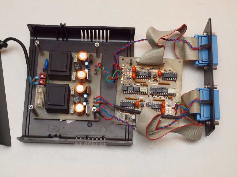 Click to enlarge the RS232 interface |
CAI BUFFER AMP
|
A NON-standard CAI buffer amplifier with a build-in amplification correction that is the reverse of the frequency dependant attenuation in a common home.
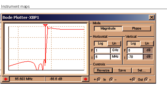
So some frequency dependant amplification correction has already been build-in, gain is about 12 dB at 450 MHz and about 18 dB at 800 MHz, no further alignment needed. So after this buffer and many meters of cable before or after it the highest and lowest UHF frequencies are equal in level!!! IP3 problems can arise caused bij too high leakage of your own internet Tx signal under 70 MHz. At the cable modem side a 300 to 1000x difference exists between Rx and Tx. (Rx between -10 to +10 dBmV, Tx between 40 - 55 dBmV). The CAI provider filter/splitter box supresses only 20 - 30 dB to the TV port. A 7-pole Butterworth 85 MHz high-pass was not sufficient, it gave only -30 dB on 65 MHz. With ELSIE (ARRL Handbook student version) I designed a 7-pole -50 dB Cauer high-pass which works perfectly! It is in a small tin box with F-connectors.
Here is the latest high dBm amplifier schematic in PDF |
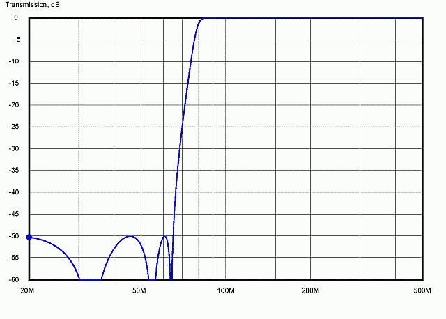 The design curves from ELSIE. Click to enlarge the picture |
 The real life simulation with standard component values. Click to enlarge the picture |
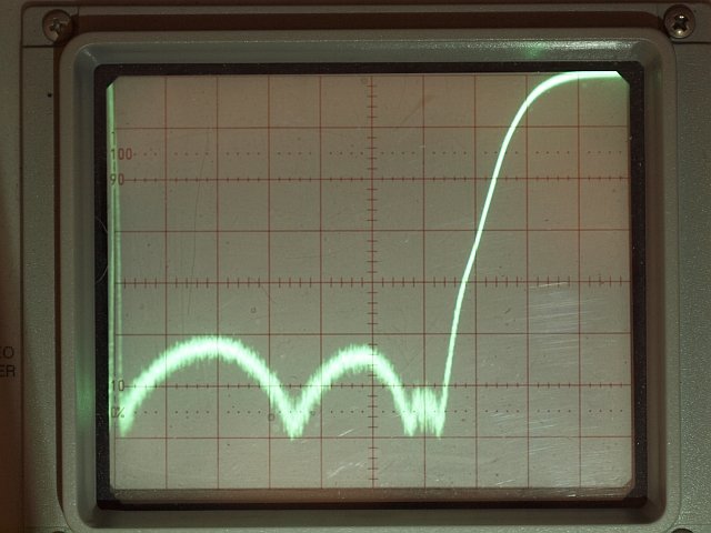 The real life performance. 10 MHz and -10 dB per division. Range 0 - 100MHz and 0 to -70dB Click to enlarge the picture |
 A look inside the tin box With pushing and pulling the coils are aligned. Click to enlarge the picture |
And then there was a modem upgrade / change, with a different Rx/Tx frequency range (cross-over moved from 65 MHz to 205 MHz) and the existing TV high-pass Cauer filter is no longer OK. Because the existing 30 dB Hirschmann amp has, to avoid cross-modulation, an internal high-pass point between 70-80 MHz, interference by the 250x stronger Tx signal up to 205 MHz is again possible. It was necessary to recalculate the Cauer filter in ELSIE The solder work is not finished yet, but here you see the component values and the possible performance. |
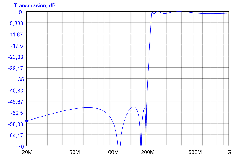 The new design curves from ELSIE. Click to enlarge the picture |
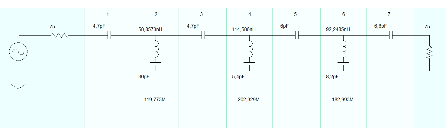 And here you see the standard Cap values. Click to enlarge the picture MY L calc software (see above ZIP) gave these winding values in Dutch |
The real life performance. 40 MHz and -10 dB per division. Range 0 - 400 MHz and 0 to -70dB 205MHz near the middle Click to enlarge the picture |
A look inside the tin box With pushing and pulling the coils are aligned. Click to enlarge the picture |
A ROBUST 12V POWER SUPPLY
|
This is a robust "extendable" 12V power cannon. Meant to feed a standard transmitter that needs about 15 Amps. It is of the old dissipative analog type. The more power you want, the more power Transistors you add with current divider resistors. Start with at least 4x 2N3772 (100V) or 2N3773 (140V). JRC used 2SD717 in their analog supply, it is a little less robust. Recently I used MJ15022 in a power Amp, also a higher voltage power cannon. The circuit is based on a SGS L200 application with good overcurrent/foldback limitation. But it is extended and more thorough tested on the edge of currentlimit and attempts to let it oscillate. Every attempt caused counter actions during the design stage!! Also an extra high power diode brigde is added ON THE OUTPUT to make it almost idiot proof by too heavy experiments. Try to understand the special way of wiring, keep to it to make it stable and also try to keep it EMC proof. The plus and minus "bar" are low impedance points on heavy output terminals, possibly enlarged with some heavy triangular copper lugs. EMC capacitors from those points with very short wiring to ground = metal frame.
Here is a schematics "sketch" set |
Here a bonus, an universal calculation example with reduced complexity: how large should my input capacitor be after the rectifier bridge? Valid for ALL circuits, from 5V DC to 1500V DC!!! It all depends only from two variables: DC current and allowable ripple Voltage. Oh yeah, and also the discharge time, which is always the same here with a 4 diode bridge or a double rectifier circuit. A 50 Hz sine = 20 milliseconds. So half a sine equals 10 msec. The ripple decay of the charge is in between 3/4 and 1/2 of half a sine = say max. 7.5 msec. Always. It is the time between some milliseconds after the top and the upgoing flank of the next charge. Single rectifier? Then times 2.33 ( 7.5 msec. compared to 7.5 + 10 = 17.5 msec)! Total charged power is in Coulomb = C x U. Allowable ripple decay part dU is delta_U x C in Coulomb. This discharge energy Q is also equal to I x delta_T. So Q decay = I x dT = dU x C , this gives a capacitor value ==> Cap = I x dT / dU . And dT = 7.5 msec in most cases. If you encounter a certain capacitor, you can calculate back what the ripple could be. And if the Cap is OK. JRC NBD500 / 520 - Cap = 68000uF, 10A dU=1.1V, 15A dU=1.6V, 20A dU=2.2V. OK? YES. Thats all, always valid. Oh yes??? |
| |
Standard 12 to 24 V supply, standard rule of thumb works. That's 2200 uF per Amp unstab.U = 15 - 30V, I = 5 Amp, ripple dU max 3V C = 5 x 7.5 x 10-3 / 3 C = 12500 uF |
|
And with lower voltage, like an analog 5 VDC with min. 3A, standard rule DOES NOT work. Its 3x more! unstab. 8 - 10V, dU = 1V ripple abs. max. C = 3 x 7.5 x 10-3 / 1 C = 22500 uF |
|
Over here a calculation for a standard tube amplifier. 250 VDC with 125 mA, dU = 10V ripple C = 0.125 x 7.5 x 10-3 / 10 C = 94 uF , lets take 100 uF |
|
And here a transmitter tube amp. 1500V DC with 500 mA, dU = 50V ripple C = 0.5 x 7.5 x 10-3 / 50 C = 75 uF, Lets put 5x 470 uF - 400V in series (with bleeders) |
|
Mains Master-Slave ON/OFF unit:
| Here you find a homebrew mains master-slave unit, copied from a Dutch Elektor magazine from 1996. Switch ON/OFF together with the master-device all the other equipment, like adapters and other complimentary equipment. Usable for a computer or radio-set as master and lots of adapters for small equipment on the slave. BE CAREFULL, EVERYTHING IS MAINS CONNECTED!!! |
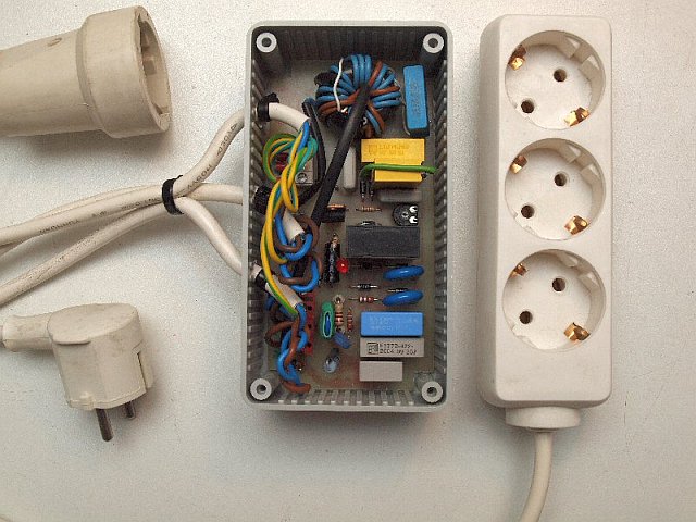
Complete set with plug and connectors |
Here is the complete story and circuit, copied from an old Dutch Elektuur (Elektor). Here is my circuit version with some changes and improvements, meanwhile a thermo fuse is added in the supply of the relay, you can see it on the picture right. Here is my latest CAD layout, the "ON" LED has its place on the board now. There is a peculiar point to mention. There is resonance effect with the toroid inductance and the capacitors in parallel to it. And: the main "ON" current lowers the inductance. The point with maximum effect = some resonance (is also a higher gate control voltage), should be at the high ON current and NOT at the "zero" current. Otherwise it won't switch off!! You have to add MORE capacitance to shift F-res to a lower inductance if it hardly switch-on and hangs for switch off. If you "plug" a test-C (1 - 3.3 uF) to lower the "zero" gate voltage KEEP IN MIND this is a HOT circuit! I've used the biggest toroid with at the same time the highest AL value ( 7000 - 10.000). You have to make some sort of fishermans knot tying lever tool to wind this type of toroid. You make it out of PCB clad, 1 cm wide and 25 to 40 cm long, use it as a wire holder during winding. See picture on the right. |
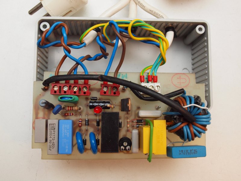
Circuit board pulled out of the box 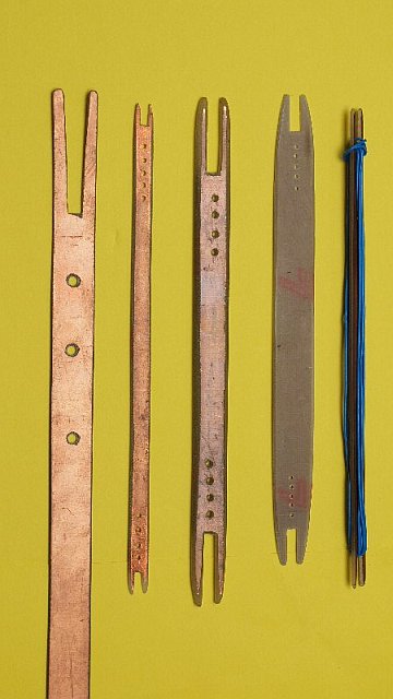
The winding tool A fishermans friend |
Homebrew counter for an Analog Rx
| An add-on counter system for an analog broadcast Rx. An example of a non-standard universal counter system (Digital readout) with cheap standard components for an old but perfect working analog receiver. In my case build-in in a Sony Rx. Fast six digit readout on FM, 3 to 5 digit on long-, medium- and shortwave, all with 1 kHz resolution, 64 msec refresh. So fast readout that follows the tuning!! Pre-load for IF substraction, two different IF's possible, with two substraction schemes ( FM / AM ). Something else than 455 kHz (468 f.i.) no problem. Ripple blanking on 3 MSB bits. Circuit tricks to buffer and amplify existing local oscillators and feed them with RG174 to the counter. NO SCANNING display readout, that's asking for trouble (beeps and whistles). Sandwich construction with three tiny boards (wire wrap experiment cards - NO CAD layout) Total enclosed in a PCB-clad box, size 1,5 times a 10/ 1.44 floppybox. EVERY LED display bit (-wire) has its own feed-through capacitor (placed even after the current limiting-R). Brightness setting with diode voltage drops. NO expensive divide by-10 pre-scale, whole counter system works with 1/64th sec. timing principle. NO expensive all-in-one chip with scanning (beeps and whistles) readout (and with only limited 4 digits)
The set with all the sketch drawings in one PDF |
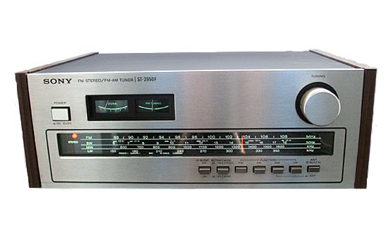 Click to enlarge the Rx front  Click to enlarge the Rx front |
Homebrew counter for a Sweeper
| Another add-on counter system for an analog 0 - 200 MHz Sweeper System. Here is another special purpose counter.... For this version the whole control system is made in SMD to make it as small as possible, as small as a tiny matchbox, for build-in in a small metal mixer box in a 0 - 200 MHz sweeper system. Overthere in the box available were input frequency as well as a marker oscillator, who now also functions as a clock oscillator. Design problem: the whole range from zero to 200, standard components don't reach 200 MHz, prescalers don't go under 50 MHz to zero. So two input circuits in parallel are needed with the same divide ratio. Somewhere (halfway) the varicap control voltage range a switchover is made from the 0 - 40/60 MHz to the 40/60 - 200 MHz input circuits that work in parallel. You don't even notice the switch-over during tuning!! Again, all because 0 to about 50 MHz is impossible for a standard ECL prescaler. More than 50 MHz from zero is possible by the use of very fast 74HC74 SMD dividers ( NO HCT !!) with a transistor buffer in front, I got the fast SMD HC74 from scrap from defective motherboards. Timing principle is comparable with the above "Sony" counter, also with 64 msec refresh. Layout boards available in SMD for control and standard layout for divider and display latch. Again with ripple blanking!
The set with all the sketch drawings in one PDF |
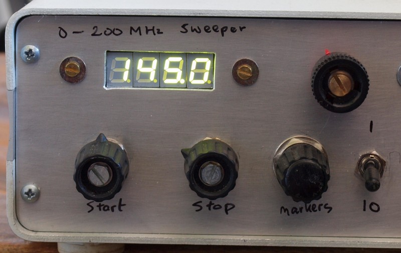 Click to see a part of the front (Not finished yet)  Click to enlarge a standard driver board 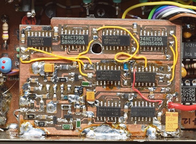 Click to enlarge the tiny control system. ECL part is on the back |
A perfect new clock radio with unfortunately mediocre DAB+ reception as standard
| (Only due to a too simple aerial wire) After my mechanical digital clock radio, more than 45 years old, had a nylon gear fracture, I gave myself a PURE Siesta Rise as a present. With DAB+. Unfortunately in the DAB+ mode only reception of some local commercial digitalradio pylons. NOT all Dutch NPO channels. With difficulty 5 channels, a few times after rescan 8, sometimes disappearing again into squelch. Is the DAB+ signal so weak inside home? FM looks OK (because transmitters use more Tx power). The antenna is unfortunately just a piece of wire that hangs out behind it. So this is next to nothing at all. My Pure Siesta Rise is working perfectly, but there has been too much cutback on the antenna connection. The device should have been equipped with an SMA antenna connection. Against all warranty provisions, I immediately took it apart and looked if I could install an SMA connector myself for an external antenna. That was feasible and succeeded. (being a professional electronics technician) On the creeper slats on the bedroom exterior wall one surrogate broadband flattened diskcone-like antenna was mounted, desinged for FM and DAB+. Consisting of 2 concentrically different sized triangles of thin stainless steel wire to the coax sheath and 2 different in size top loads to the inner coax wire. Over the outside coax cable some common mode current ferrite blocks and between the inner conductor and ground one static short-circuit coil with a mini 14 mm 4A11 core with N = 5. Result? Immediately 25 different stations in DAB+. Fine, reception problem solved. Thin Teflon coax is used from the radio SMA connector up to 1.5 meters under the bed. Outwards with RG-58. Neater and more stable on the bedside table. See picture. Months later, when there was a vertical Log-Periodic (80 - 500 MHz) in the mast mounted (also for FM, DAB and DVB-T), this antenna once tested, gosh, now more than 45 DAB+ stations, including Flemish. Once again: out of the box in original state 5 to 8!!! While switching the BNC plugs between aerials I got a serious mains current shock. The 5V mini USB power supply is apparently not sufficiently leak-proof and has a little too high mains leakage current. Needed to take the PURE apart again. Now an earth current / common mode separation made with 1x 470 pF - 2 kV in the inner conductor and 2 (to 3) times 470 pF in the ground/shield. As in the past was standard used in the tuners of picture glastube TV sets with mains connected inner frame and is still used in cable subscriber takeover boxes. Another problem solved. The following problem reveals itself. While ALL antennas are grounded in an outside wall-connection box, I now notice that suddenly a new light grunt interference from 0 - 2 MHz on my DX radio in the shack. Which appears to come from the 5V adapter. Due to lack of space, there is also too much cut back on this item. So I left that adapter closed. I mounted in between (adapter and mains) a piece of twin mainscord wound on top of three stacked +/- 32 to 36 mm high AL dump ferrite toroids (min. N = 8), provided with plug and counterplug (counterplug very close near the cores and USB adapter) and thrown this under the bed. Interference almost disappeared completely. Epilogue: Why can't they, when designing such a beautiful device, pay a little more attention to 1) EMC common mode suppression of the switching power supply and 2) more enjoyment of reception by providing an extra antenna connector? |
 Click to enlage  Click to enlarge |
 If you do not have the "Acrobat Reader",
please access to the site of Adobe Systems Incorporated.
The Acrobat Reader is distributed by Adobe
Systems Incorporated free of charge.
Adobe, Acrobat Reader, and their logo marks are registered
trademarks of Adobe Systems Incorporated.
| A short visit to the "inventors" workshop, all the talk is in Dutch and there are no subtitles. Play in slow motion to see all the details!! Video Title: "May I come in for a short visit?" - part 10 - The Inventor Video copyright: |
Site copyright © 2001 - 2016 Walter Geeraert - All Rights Reserved
|
|
|
radio.htm
by Walter - PE1ABR - 2024-03-04