|
A collection of ferrite toroid related hobby research spin-offs |
|
Some handy stuff for the occasional ferrite user |
© PROJECT ENGINEER: WALTER - PE1ABR Zie je liever een Nederlandse versie?? Klik op de vlag of HIER |
|
Directly to the sub-page with results and explanation of the many measurements and
the processing with Ferricalc and Excel. To the cinema! YouTube ferrite page The pictures are all clickable for larger versions and/or PDF Material overview Ferrite and/or Powder Iron What kind of stuff is it?? How is it made?? 
↑ Overview PDF 
↑ 3C11 - WHITE 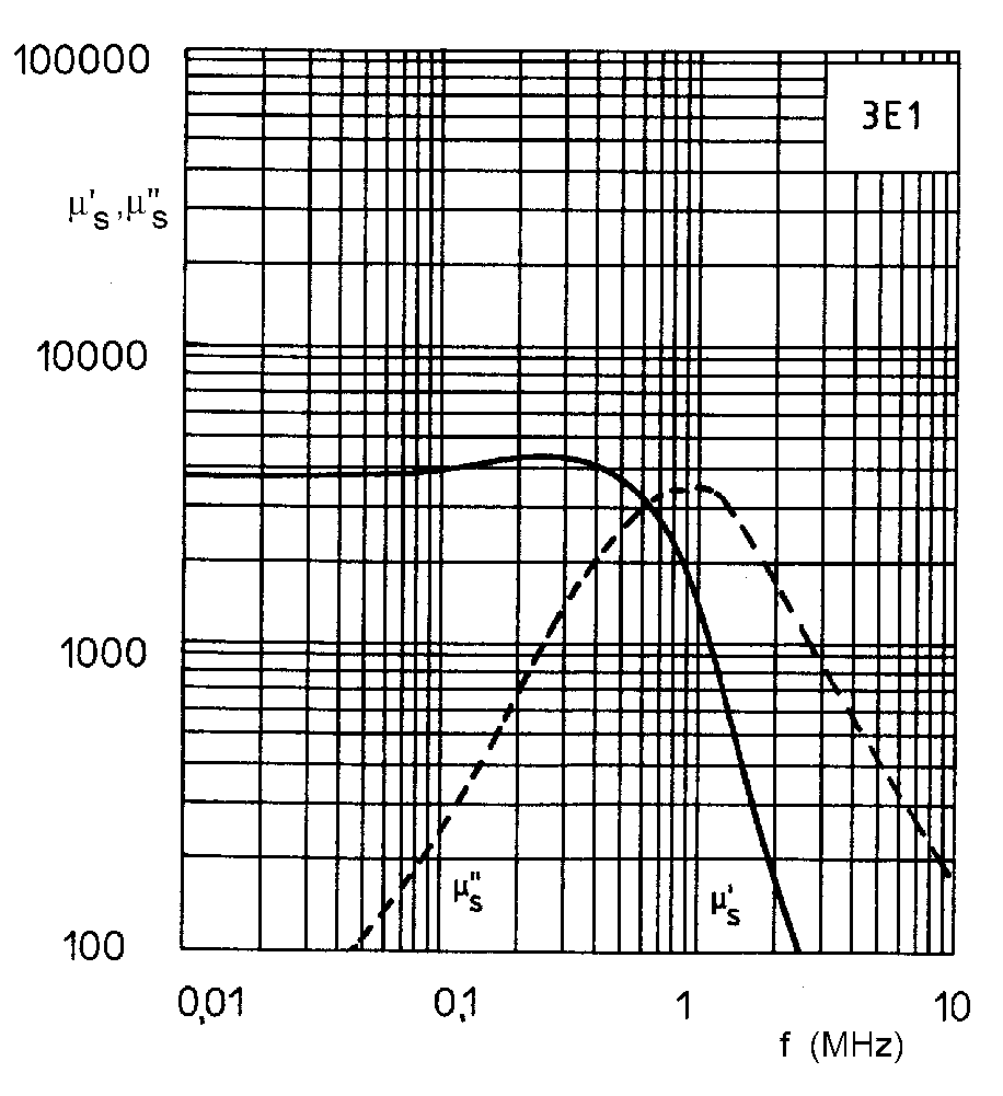
↑ Old 3E1 - GREEN 
↑ 3E25 - ORANGE 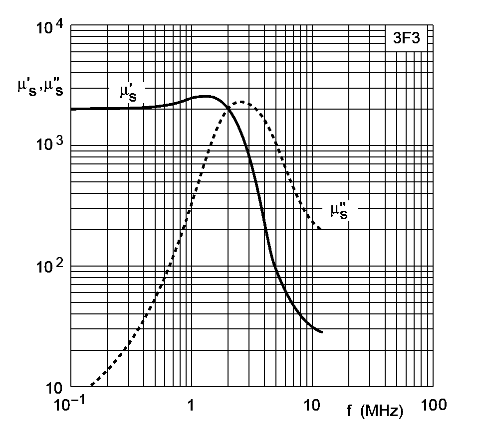
↑ 3F3 - DARKBLUE 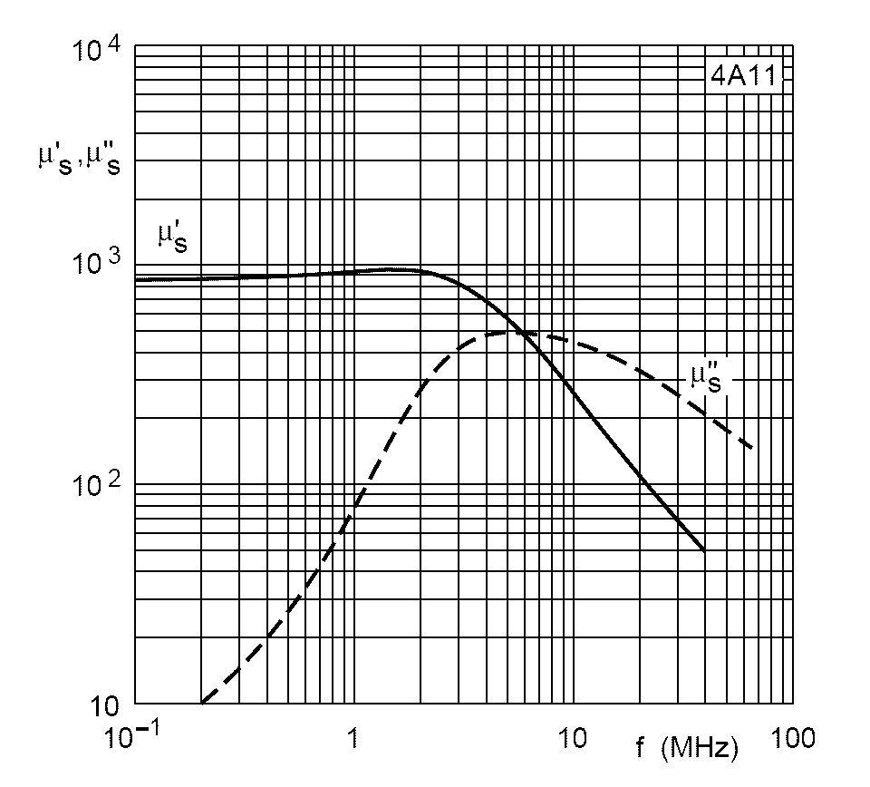
↑ 4A11 - PINK 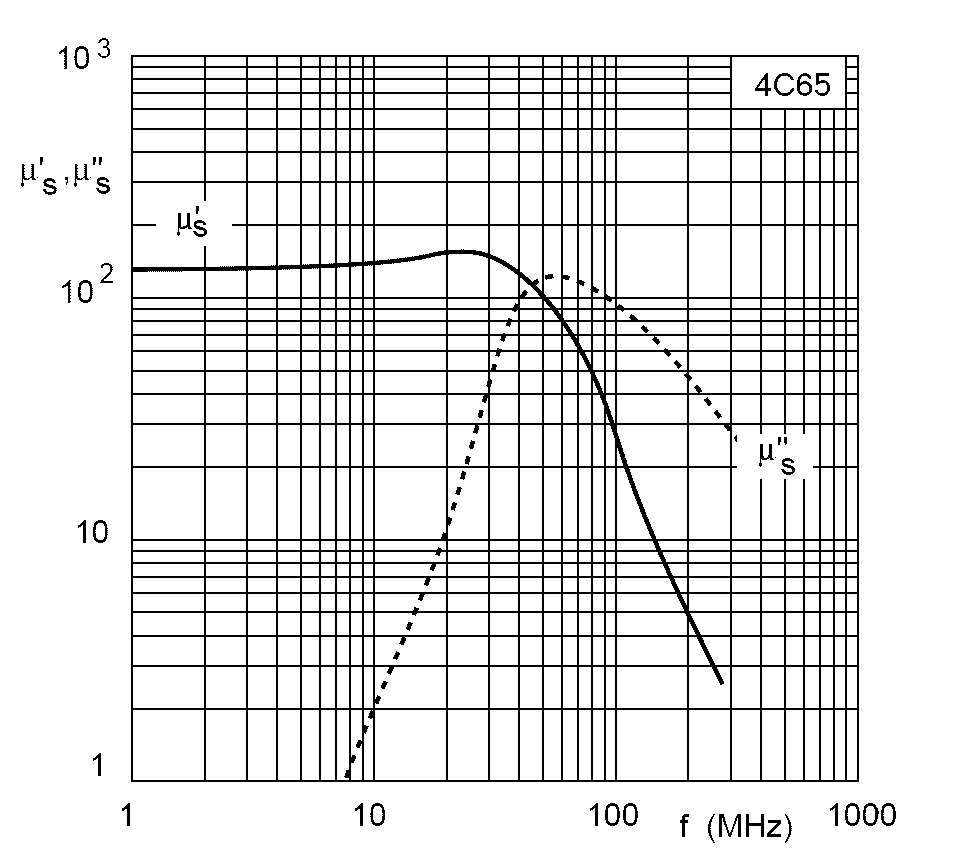
↑ 4C6 or 4C65 - VIOLET 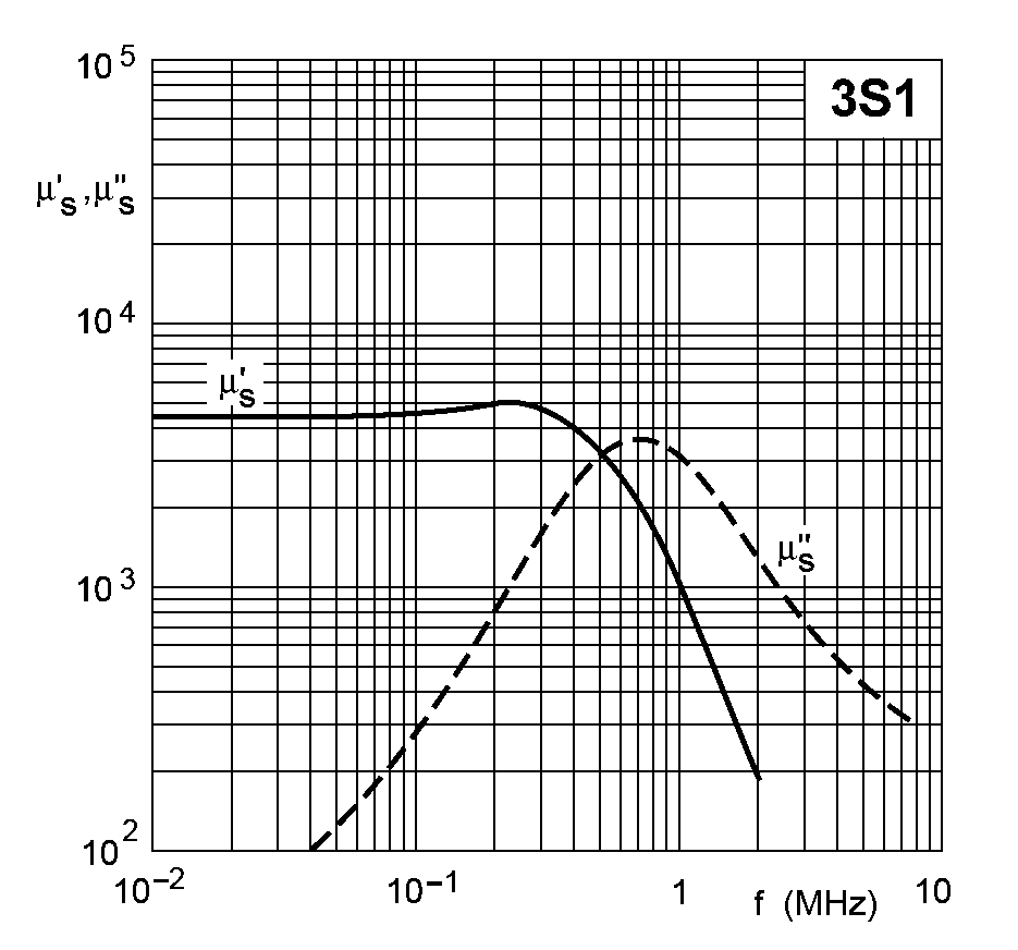
↑ 3S1 Low freq. EMC 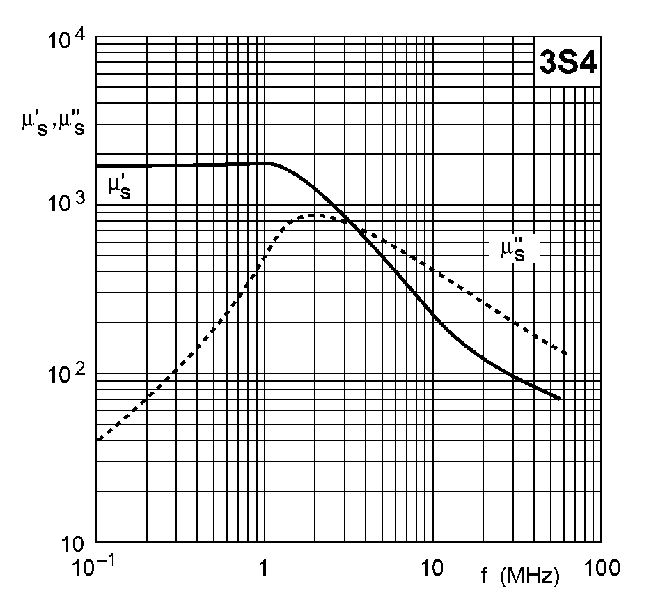
↑ 3S4 Wideband EMC 
↑ 4S2 High freq. wideband EMC |
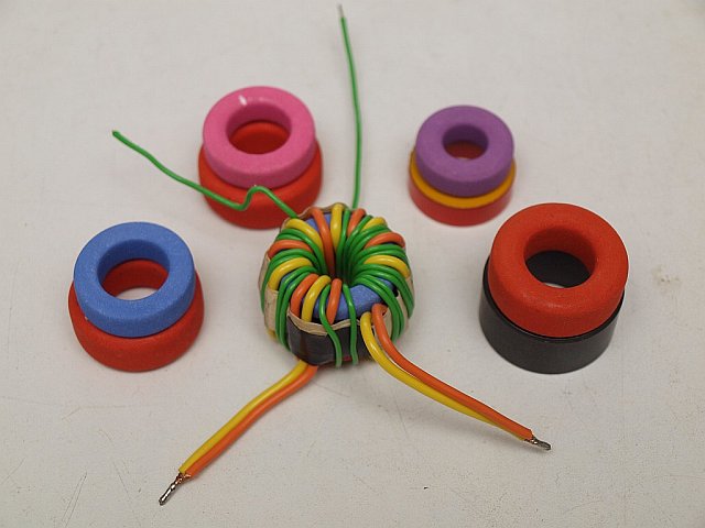
Just like iron (or better : silicon-steel) is a practical magnetic material for low frequencies (f.i. in mains transformers), for higher frequencies ferrite is a handy and better material.
Ferrite "to the bone" is nothing else than a ceramic (dual-)crystal shape of iron-oxide - a kind of baked rust......
Unfortunately the electrical conduction is far too high, so the losses too much.
With a trick science found a solution, that is they deliberately polluted the crystal form with other oxide-materials that reduced conductivity between the tiny local microcrystal areas. And at the same time try to keep the magnetic properties or amplify them. The resulting mixed crystal shape is called like comparable natural minerals
spinel.
Dependent on the kind of additions, the magnetic properties become gradually less and the electrical resistance higher and higher. And the usable frequency also gets gradually higher. See the upper picture left with some (ex-)Philips types, more and more a bit lower and at the same time higher in frequency. What you don't see are curves of the losses. Those are the dashed lines in the individual material curves. More about them later. About the oxide-mixtures that are added: more "tastes" have evolved. Variations with CuZn and MgZn oxides were rapidly abandoned. The two main types are: either MnZnFe(II)- , or NiZnFe(II)-oxide mix in duo spinel crystals with Fe2O3 iron(III) -oxide (= ferrite). The main components after ferrite itself are either manganese-zinc (MnZn) or nickel-zinc (NiZn) oxide. And some more other metal oxides, a.o. vanadium Va, copper Cu, magnesium Mg, cobalt Co, tin Sn, and probably many other secret materials. After the mixing of the oxide powders in the required dosages and pressing them into small cubes, they are given a first calcining (= sinter) action. Afterwards again ball-milling to a powder, sometimes wet to a slurry, and mixed with a binding agent. After pressing of the desired shape or toroid it is dried and sintered again to become the final product. After the double sintering (annealing) action cubic spinel crystals (5 to 30 micrometers) arise with still reasonable conductivity, but isolated from each other by the non crystallized remains between the crystals in the boundaries. The resistance of the boundaries can be one million times higher than within the crystals. Special boundaries pollutions are used, like Calcium (Ca), Silicium (Si) and Titanium (Ti) to achieve this. Probably also ZnO - zinc oxide remains. Titanium is also diffused within the crystals to control the temperature dependance. Cobalt (Co) additions are also being used to stabilize temperature dependance, but can give a second peak in the mu/temperature curve, just like an overconcentration of Fe2+ ions also give this effect. Manganese-zinc as mix for ferrite gives a still noticeable (with an ohm meter measurable) conductivity and rather high magnetic properties. Nickel-zinc as addition reduces the magnetic properties much more and gives a very high (almost immeasurable) electrical resistance. Higher frequencies demand for very low losses due to the higher number of magnetisations per second. And a too high magnetic property is also undesirable, so all OK, each variation of "taste" has its own use. Another word to avoid confusion between two magnetic concepts: The ferrite material constant at extremely small field strengths in a closed system, whatever its size, is called the mu (µ). This can be seen as the "gain" compared to air. Also called the µi, the initial permeability. This is the material property that you see everywhere in the tables, it is independent of the core design or shape. The relative self-induction of one specific core, with all data in it, a parameter of core thickness, core length and the typical mu of the core material is called the AL or AL value. Note: For cores between 30 and 40 millimeters, depending on the thickness, the conversion factor of the length / surface average and AL is around the factor "1". Make sure you take the AL, which belongs to the core and not the mu! The magnetic conductivity properties combined with the shape (square diameter and length) properties can be expressed in a practical standard value for each make and type of toroid: the AL value, or better written down: AL value. It expresses the number of nanoHenries per turn, or millihenries per 1000 turns. For both expressions it stays the same AL value "number". One more time: The ferrite property independent of the shape is called the mu (µ). The optimal range of use for MnZn- and NiZn-ferrite have some overlap, where MnZn is usable from LF to 0.25 - 2 MHz, NiZn can be used from 1 MHz to far beyond 100 MHz for energy transfer (= transmitters). With limitations it is even used up to 1 GHz. It all can be seen nicely in the upper picture where the magnetic property mu (µ) for a number of materials is plotted against the frequency. NiZn mu (µ) between < 50 and 750 and MnZn from 1000 to 15000. The average AL value (depends on geometric properties) goes for "average" toroids between 1000 - 15000 for MnZn and for NiZn from about 10 to about 1000. Average is a toroid between 10 mm and 36 mm. In this Philips picture MnZn is the type starting with a "3" and NiZn is the material type starting with a "4". [A little history: Around 1930 - 1934 Japan was far ahead with scientific CuZn ferrite research by T. Takei and V. Kato (founders TDK!). Producing and obtaining a predictable final product was however a major problem. After about 10 years of research, J.L. Snoek (Philips Nat.Lab) patented in 1941 perfect production methods for Ferroxcube-I CuZn ferrite (type 1 ==> eg 1Zxx), Ferroxcube-II MgZn ferrite (type 2), Ferroxcube-III MnZn ferrite (type 3 ==> known 3Bxx eg, 3Cxx, 3Dxx, 3Exx, 3Fxx, 3Hxx), Ferroxcube-IV NiZn ferrite (type 4 ==> known 4Axx eg, 4Bxx, 4Cxx, 4Dxx, 4Exx), Ferroxcube-V Mn ferrite (type 5 ==> only for transformer cores) The production started only after 1945. Just in time for use in TV sets in the lineoutput stage and the deflection yoke! Also read this document on the site of IEEE - Scanning Our Past From The Netherlands - IEEE Xplore, or a copy on my own home server. Later development: the use as computer memory core. Ferrite type 6 ! Many different ferrite material types have been developed, especially with the aim of the smallest possible dimensions. Design goal was here with recipy-6 to obtain a BH-curve not as slim as all the other ferrite types, but as square as possible. In the 1960's Philips / Ferroxcube core types 6E1, 6D5, 6D9, 6C1, 6C2, 6F3, 6F8, 6H2, 6H3, 6H4, 6H5, 6H9, 6H6, 6V2 were available. The tiny cores were as small as 0.355 mm (14mil) to about 4 mm (150mil) outer diameter. Look at the last page of this PDF overview. Only (Philips / Ferroxcube) metaloxide mixes for the ferrites type 3 and 4 are apparently applicable nowadays! And in use by all copycats worldwide. Well, not just copycats, Philips has traded patents, manufacturing methods and licenses with some American companies. This gave Philips, among other things, licenses for semiconductor manufacturing. ] For EMC and suppression applications the loss factor is an enhancing factor, it is added to the inductance Z. In this case they form together a complex impedance via Ztot = ZXL + jR . It is not different from this: Ztot = √((2 . pi . f . L )2 + R2) In EMC applications there is NO energy transfer, energy should be absorbed! What you can say about mains oriented electronics for coils and resistors, you can speak about real (R) and imaginary (L) impedances, you can also say about EMC ferrites: you have a lossless SELF-INDUCTANCE part (ZXL) and a complex LOSSY part (jR). But compared to mains electronics real and imaginary are somewhat "twisted" in their meaning.....! Just to emphasize: No ferrite has a stable fixed value mu. All ferrites have a frequency at which the inductance effect collapses to ZERO. So they have a typical "terminal value". At the bend in the curve losses rise exponentially! For "power (voltage) applications" preferably as late as possible a rising "dotted" graph. Click to see once more the Philips collection image (also top-left). Especially for EMC application (and guanella type common-mode suppressors!) this part of the dotted curve is deliberately increased and given a broad back. The total Z in this type of application is composed of a L Z-part added with a R Z-part together! For HF ("voltage") transformer and resonance applications you'd rather NOT use this type. Material which has been made to obtain the opposite effect - as tight/low as possible dotted curve - is called "low-loss" in the Cros_Ref_list. Except ferrite, microscopic fine iron powder is also used as toroid material in combination with a clay (becomes → ceramic) binder. Low frequency ripple chokes in switch-PSU's power applications or cheap mains-filters (light-dimmers) mostly use "standard" iron powder. Also a special nickel-iron powder mix is common. There are powder iron cores available with only low frequency application (hydrogen reduced Fe-oxide), depending on the type only from max. 10 kHz to max. 1 MHz usable. Usually for power supplies and filtering. The main advantage compared to ferrite is a to 4x higher saturation. When applied to these low frequencies, so no HF requirements needed, in fact, they have a very low Q at HF frequencies and suppress these just much better by absorption and without resonance glitch effects. So for HF purposes this kind of (nickel-) iron powder toroid is useless! The iron powder for HF application cores is chemically made by reducing iron-containing chemicals ( Fe-pentacarbonyl) with the "charcoal" principle. It gives microscopic fine isolated (foam or shell-like) iron dust. Almost all the Amidon iron powderdust toroids are of this kind. Made by Micrometals. Keep in mind: compared to ferrite this material has an extreme low magnetic property. Amidon powder materials µ is in the range: between 5 and 30 !! So the average iron powder AL value for 25 to 40 mm cores is also between 5 and 30 (nH/turn or mH/1000 turns). When expressed in the same order of magnitude (units) as ferrite! = nH / winding or mH/1000 windings. Posted in the Philips collection image chart top-left it is on the "zero" line or one indent above. To make it prone for error: due to these low values for iron powder cores the industry has chosen a different ALstandard!! It is a factor 10 higher and overcomes the need to use iron powder AL values with a decimal point in it. They therefore express the AL value in microHenry (µH) per 100 turns!! If you are going to use (my) standard formulae take notice of the fact that you have to divide ALL Amidon iron powder values by 10 to use the same calculating method!! |

↑ Fair_Rite / Amidon 77 material comparable to ex-Philips 3F3 blue |

↑ Fair_Rite / Amidon 43 material comparable to ex-Philips 4A11 pink |

↑ Fair_Rite / Amidon 61 material comparable to ex-Philips 4C65 violet |
How do I make the right ferrite choice?? 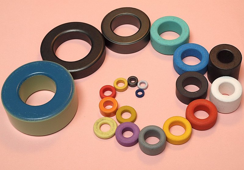
Try it 100 times??? 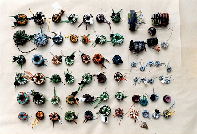
How does it behave with (power) losses?? 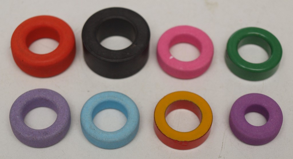
The voltage E over a coil on a ferrite toroid belongs to an certain induction value B: E = 4.44 . f . N . B . Ae . 10-9 and Bmax = Emax . 109 / 4.44 . f . N . Ae If you start with a given current I (50Hz current clamp): Bmax = N . AL . I . √2 / Ae N = winding number, f = frequency in Hz, Ae = effective surface area in mm2 and B in milliTesla |
The ferrite or iron powder choice is demanded mostly by the application and circuit impedances. If you use ferrites for resonance circuits (high impedances) you have to be careful to make a choice or you run into trouble!! Already at low frequencies the circuit damping by ferrite losses is such that the max. reachable Q is seriously spoiled by the loss factor. A resonance circuit is NOT a low-ohmic transformer application, but a high-ohmic tuned LC-circuit. Eddy Current loss effects The loss characteristics are the dashed lines in the ferrite pictures above. They rise slowly at first, but around the AL nod they rise strongly with the increase of the frequency. If the value rises above 5 to 10% of the non-dashed curve, the material is less-ideal for resonant LC applications. At 25% of the value worthless! NOT the LC and the load dictates the Q, but the losses then do! During experiments I drew my own limits at about 7.5%. An example of the resulting limits for resonance applications: 4C65 and FT xx-61 = ±15MHz, 4A11 and FT xx-43 = ±700KHz, 3F3 = ±400KHz, 3C85 and FT xx-77 = ±200KHz, 3C11 = ±100KHz en 3E25 = ±80KHz !!! The loss factor has also influence in normal "voltage" transformers at power applications. Heat !! If impedances are low and you make a good NiZn choice, all goes well. (the circuit range Z from 10 - 250 ohm is commonly used...) Used in applications without power (induction B = < 1 milliTesla) and again: low impedances (like in Rx and data transfer = ethernet), MnZn is not such a problem. You only have to take into account that there could be a parasitic ballast-R due to losses. And: the magnetic properties are to decrease further with the increase of f to ZERO! The BHmax problem, the magnitude of the magnetization The applied field strength outside the core corresponds to the number of turns times the current. This gives an external field strength H, expressed in A/m. The effective magnetization (induction) B in the toroid is NOT linearly proportional to H, but has a saturation (= end) value. Then, the function of the ferrite disappears! B which is usually expressed in milli-Tesla. Approaching saturation (being not linear) and the continuous polarity change of the field causes this type of loss. The maximum permissible voltage across a coil in a ferrite core goes up along with the frequency. That is to say the lowest frequency for this type of loss determines the core size. For RF power application never go above 20% ( = 0.2 times) of the maximum B specified by the manufacturer. The factor 4.44 in the column left becomes 4.44 times 0.2 = 0.89. The max. coil voltage E in our baluns is thus E = 0.89 . f . N . B . Ae . 10-9 N = winding number, f = frequency in Hz, Ae effective surface area in mm2 and B in milliTesla. Please note at other web sites whether this is expressed in Gauss or Tesla! The factor 10-9 could be different. The magnetization effect is in principle, especially when overdriven, NOT linear! There may therefore be at least, except heat, also arise of a third harmonic! Used in current (= transmission line) transformers and EMC purposes (= common mode suppressor, see further down) the main HF current is not a problem, it cancels out! The common mode current that must be suppressed is now demanding. Thus, a sufficiently high value with low para-C. Because this current is suppressed and partly by the application (eg symmetric to asymmetric and excessive impedances after the faulty use of a tuner), it creates a high voltage across the inductance of the cable on the ringcore. This voltage is therefore generated by the flux-changes in the core as back-EMF in order to suppress this current. If the external voltage over the choke balun becomes too high or too short of core material surface area is used (the flux-change does not reach the required back-EMF voltage), then the core is saturated due to a too high HF current and gets burning hot due to power absorbtion. This is the main problem at low frequencies caused by Bmax limit of 20% Bsat. On the other hand at high frequencies, where Bmax is not the limiting factor but by a too tight core choice, there still too much dissipation could occur by eddy currents and it also goes wrong. Either the windings flies into fire, or the core disassembles with a bang! The only method that works is much more core surface area (divide fluxenergy over more cores and / or winding units with low parasitic capacitance, see picture) and also no false application were too high impedances may occur. This increases the voltage strongly and the problems! Voltage according to P = U2 / R , play with 10, 100, 1000 W and 5 (semiconductor amplifier), 50, 500 and 5000 Ohm!! But for resonance circuits iron powder cores are mostly a better choice. Dependent of the frequency range only the better NiZn is only usable from 100kHz to max. 10 to 15 MHz. It is always a compromise between the number of turns and the material choice. The higher the AL value the worse for resonance on higher frequencies. And the problem with the lower AL value: a unrealistic number of turns. So stacking toroids could be a solution. More toroid calculations can be found on Dicks website. |
| How many windings are needed for a certain inductance??
Calculate AL with the f-res test 
My own Software for above!! FERRICALC ZIP file with EXE and Postscript overlay sheet. See further down. |
Make a ferrite choice with the minimum frequency in mind. Do NOT go as low as possible, but try to find what is usable with a very limited number (5 to 8) of turns for the Zmin. If you have measured them yourself, this is probably the material with the best Q. In the links further down you can find some "extracts" (in DUTCH) from my booklet with calculation tricks to calculate fmin at N=x (x = 5 to 8) for a number of toroids that you have in stock. The maximum (8) is, in many cases, already a problem for 20-30 MHz (too high para-C).
For 50 Ohm circuits also choose Zmin = 4 times 50 = 200 Ohm as minimum coil impedance. Use the AL value that belongs to that toroid (in a manufacturers table or in your home made ones), use the appropriate formulae N = 1000.√(L/AL) and finished. Get my AL table extract (in DUTCH) from "Ferrite Info" in PDF, with also extra explanation. There's a lack of space over here. Some further down another extract about measuring is spoken off. Get it now already. Click here But how do you get those AL values from unknown toroids?? Again: further down.... |
|
Directly to the sub-page with results and explanation of the many measurements and
the processing with Ferricalc and Excel. How do I make measurements??  Measuring with the TOP-R method
 Or with the TOP-C method
 My handy measuring cable in Elektor!
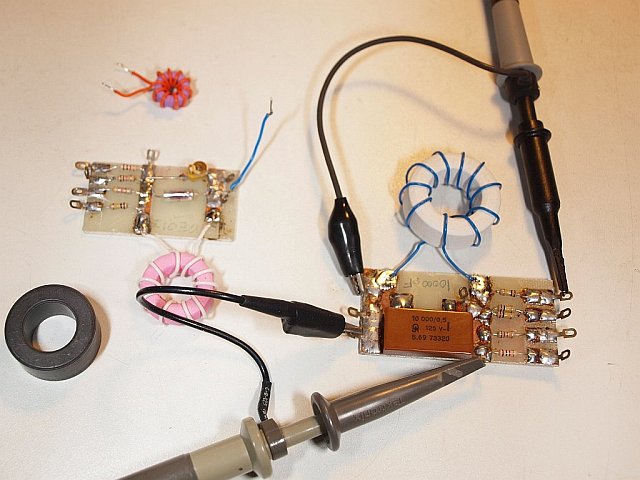 The first older modules
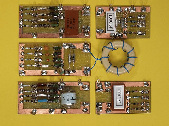 The improved rebuild modules
Although: the rolled-C bottom-left is rejected... 
The above animation is now also clickable to enlarge it! My own calculation Software!! switchable between NL and the UK It are basically two programs now in one EXE, one for calculation and one for documentation. The calculation result is transferred to the second program window. The results are patched as an EPS print-overlay part in the original empty postscript *.PS print file. (The fill-in sheet) This *.PS file should be available in the same folder. The postscript sheet is also in the ZIP. 
↑ An empty example to fill-in in PDF (UK/English version) programmed 2x on 1 A4 sheet (1x = equal to the EPS overlay) |
Standard ferrite properties (a.o. the µ and AL value) are only measured reliable and simple without too much parasitic effects only on rather low frequencies.
Because also the (too huge) number of windings has a parasitic effect, a nice agreement is: 10 windings divided over the total circumference, no more and no less. 10 = the number of turns through the centre hole, NOT the turns visible on the outside!! Think about a current clamp → 1 pass = 1 total winding!
Also keep this in mind: only with exactly 10 windings on a toroid you can have a direct fast impression of the AL value on a coil (L-)meter. Because only for 10 windings is valid: AL value = shown µH value x 10. Which works only if the coil meter measures on a low frequency before the decay in magnetic µ properties!!!! Measuring the AL of most unknown ferrites with a dipper (or MFJ device or RF-Analyst) gives due to too high frequencies and/or a too low parallel capacitance NONSENSE results! See article in Elektor written by PE1ABR for more background information about direct AL readout. Published in the UK (and Germany, France, the Netherlands, etc.). To reduce parasitic toroid and C effects a first measurement with at least 10 nF (<1%) in parallel is OK. Otherwise the resonant frequency is far too high. A second (additional) measure, for material with a relative high AL value (above 2000 - 3500), is a second measure with 100nF, 1uF or 10uF (<1%) in parallel. The values for AL shouldn't differ too much, although the Q mostly is more advantageous. The used capacitor values should be verified on a RCL bridge or aiding-oscillator circuit. Also keep in mind to add the scope probe capacitance if measuring with 10nF or lower!! See further down. Another measurement can be added for higher AL material: for a better "total" view test it also with 25 windings and the same capacitor. With a 10x bigger C and/or a larger winding number you get more "down" to the smoother part of the AL (or better : mu) curve, see the top picture for an overview. Very low capacitance values (under 1 nF) gives more unwanted parasitic effects and make the measurement completely unusable. As well as with a low-ohmic current link as well as a high impedance voltage link errors may occur. Mostly in the Q value, hardly in the AL. Some sort of high impedance series R-link is also used by the industry (Murata, for their IF filter coils), that method appeared handy. On the other hand, a current link, feeding a link from an impedance under 10 Ohms, looks more like a short circuit, so unusable in my opinion to make a reliable undamped (!!) Q measurement in this circuit. An oscilloscope 10 MegaOhm probe is in parallel (with its capacitance from about 15 - 25 pF, → add it !!) to the LC circuit. As a feeding control signal we use a simple sine generator from LF to about 2 - 5 MHz. For very small NiZn toroids (under 10 mm) this is sometimes not high enough. Better use a higher parallel capacitor instead to reduce the resonant frequency. At the end of the feeding coax-cable it is advicable to add a 50 Ohm terminator R, and from this point the high feeding R to the LC measuring circuit. For the ease of use, and if not too long cables are used, it is possible to misuse an uncompensated 1x scope probe as feeding cable to the series R's. (a probe without any R or C correction and used backwards). For the ease of use it has a nice clip to attach, see picture. Via this series R, a choice from the values 1K, 10K, 50K and 100K Ohm (or more..., up to 500 kOhm..), the signal goes to the LC circuit. The f-res is found by quickly tune the whole frequency range of the generator, under use of the lowest series R. Otherwise you could "fly over it", it could be difficult to find. After that use the highest possible value. You have the least degradation in Q due to the highest resistor. Higher than 500 K is unrealistic, because the parasitic C gets an equally large (or even lower) Z. Although a scope is the most easiest to work with as an indicator, an amplified HF millivoltmeter also could work. It all depends on the max generator voltage, sensitivity of the scope/millivoltmeter and also the losses in the ferrite. After reading technical papers from others (eg. ON9CVD), is measuring, NOT with a high feed-R, but with a very small feed-C, also a very good (or even better) method. I have added jumper selectable capacitor steps between 1 and 0.1% of the reference C. Also, not measuring with two, but with much MORE versions of the test module with 100pF, 1 nF, 10 nF and 100 nF (and also 1uF, 10uF and 33% values in between) gives a better "overall" view of the effect of the "inclined plane" of the mu curve. Because: some types (high AL) and ferrite mainsfilter EMC-cores you can judge better with a much larger measuring C, not 10 nF e.g. but 100 nF and 1 uF (or even 10 uF!). You are measuring then purely LF (in the audio region). These higher C values MUST be with an extremely low own self-inductance (or D = lossfactor), otherwise the equivalent Rs (or Rp) is determined by the C and not by the coils losses. Make them by paralleling 10 smaller values (So: 10x 10nF = 100nF, 10x 100nF = 1uF, 10x 1uF = 10uF). The large accurate rolled foil-C in the picture is therefore now rejected for having too high losses! See further down at Q and B√2. Most worst ferrite (MnZn with the highest AL and / or the lowest "kink") did indeed gave only with the 100 nF Cap. (or higher) realistic Q measurement results. The once-selling light-blue 23 mm Philips toroids appeared useless just above 20 kHz!!!!!!!!!!! If you want to calculate accurately after using the TOP-C modules, for each branch-C the corresponding different ref-C value must applied. That's again a slight disadvantage. The main advantage is that you no longer need to take the supply-R damping into account. Look at the TOP-R drawing or the TOP-C drawing in PDF. From these measuring aids on a piece of clad board you need at least THREE, more even better! Meanwhile I have 16 modules! UPDATE: after the purchase of a Mastech MS5308 LCR Meter and also the construction of the Elektor microprocessor RCL meter it is now possible to measure the dissipation factor D of capacitors up to 3 digits after the decimal point (= up to 1 per mille). Above 2 permille at 1 kHz (D = 0.002) is asking for difficulties. The 3 modules with the largest C values (350 nF, 1000 and 10000 nF) were NOT OK. They have been rebuilt. This gives a much better Rs curve in the low! However, not many capacitors meet this requirement! The WIMA FKP series, however, has D values below 1 per mille. Even at 10 kHz! also see both IMAGES left. In this GIF movie you see 16 modules passing by!. The new modules in the picture are made slightly different than in the drawing. The drawing was already finished ...... Principle is the exactly the same, but the typical changes are untidy on the drawing. In the picture the jumpers are placed between the Cref-trace and the four C-tap's. Each C-tap capacitor after the jumper has here its own 50 ohm dummy-R to ground. Because of this the other C-tap's that are not used form no parasitic load present at C-Cref. As shown in the drawing: only one time a 50 ohm dummy, a set of jumpers, and then C-tap's, all connected to the Cref as shown, is also possible. 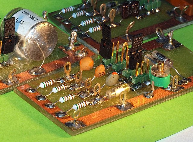 Etching is not needed, a sharp knife or dental milling tool works fine (need for plasters??).
 To reduce parasitics you should remove unneeded copper. However: To minimize effects of hum and RF noise, there is a single-sided PCB groundplane mounted underneath. Click on picture next right to see some details. QB√2 The ferrite quality (max. usable f and losses at f-res) can be judged by comparing the Q at f-res from different measured toroids. Or with an identical measurement on a different Cref module. The Q follows out of the two 70% points f1 and f2 next to f-res (±70% = -3dB = B-sq.root-2 = B√2) and put in the formulae ( QB√2 = f-res/(f1-f2) ) This can be corrected - series R damping effect removed - to calculate the real Q without the feeding R. This correction depends strongly on parallel C and frequency. You need a correction graph for every measuring module, and also every series R variation, you make. To encourage everyone to take toroid measurements, I have put all the formulas in a Windows VB6 program and made it a little "idiot-proof". Also the Q correction calculation is now automatic. That's easy! In a later version of the program additional formulas were added to compute from the Q, f and parallel-C the equivalent series-Rs and parallel-Rp. For an important core (4C65) I have once put them into graphs. It was found (after years of measurements) that the 100 nF module capacitor was bad, too high a Rs. Because it was a "rolled-C", it's that one in the small picture above! In addition to the series modules already mentioned above: with values 100 pF, 1 nF, 10 nF, 100nF, 1uF and 10uF (preferably all with MULTI C parallel setup), I have made some extra intermediate modules: 330 pF, 3n3, 33nF and 330 nF. That gave some additional intermediate Rs/Rp points in the graph's. Also, the small C values are found to perform better (higher Q) when built up from several smaller parallel C's. For every toroid you intensely measured you can keep a "datasheet" page in a small A5 binder. In the latest Ferricalc version the documentation module is build-in. But start with a few well-known toroids to get familiar..... Much more additional information about the measuring method, formulae and Q-correction tricks in the following piece taken from the booklet "Ferriet Info" IN THE DUTCH LANGUAGE!! Click over here for the DUTCH document in PDF |
↑ Example filled in by hand in a PDF |
Click icon to get VB6 runtime and OCX files for FERRICALC if needed. Even the VB6 .HLP files work with Windows10 with the help from this link |
↑ complete fill-in with the EPS overlay (PDF) in Ferricalc version 3 (same toroid) |
How should it be winded?? Current and voltage transfer 
The strong negative impact of the para-C already at low winding numbers. 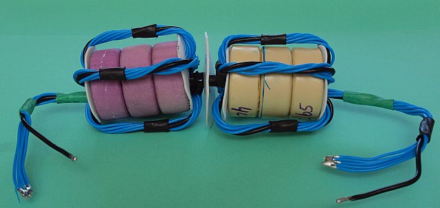
A Guanella wideband 50 ohm in/out common mode suppression filter with very low I/O capacitance.  ↑ PDF
↑ PDF
 ↑ PDF
↑ PDF

Analyzer result for 2 above 1:9 toroids in series/cascade (50 → 450 → 50 ohms). Calculated start 140 kHz, but usable from < 50 kHz, flat to approx. 33 MHz, -3 dB = 45 MHz, -6 dB = 50 MHz, and -10 dB = 55 MHz. Not bad at all for a "simple" voltage converter. 
|
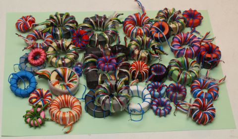
How to wind?? Depends on the application, is it a current transformer or voltage transformer. current transformer A "current" transformer usually consists of one or more transmission lines between in- and output with strong common mode suppression. The international name is "transmission line transformer". Common mode currents are suppressed by the choke effect. The (bifilar) winding wires form, just like HF-cabling, a fixed constant impedance on the cores. The parasitic capacitance is part of the cabling strains impedance and doesn't harm. The capacity to or through the core, or even over the core (from out to in) is a serious pain. Optionally, therefore, properly constructed into sections. By adding more branches, in parallel on one side and in series at the other, an impedance transfer is accomplished. Those windings made with double (bifilar) wire are extremely tightly twisted, sometimes even in (teflon) sleeves because of the stability of the Z. The mechanical construction of the strains is such that they form the ideal impedance to sum or divide to the right value on each side to match the connected impedance. An example: Two strains of 100 Ohm cabling on the cores form 50 Ohms parallel on one side and 2 times 100 Ohm = 200 Ohms in series at the other side. The common mode choke value must be at least many times the connected impedance. Up to 10x to 25x the impedance, also with a very low parasitic C between input and output. Because the Z of a single toroid mostly is not enough, (many) more toroids are stacked. Problem: If a NON-ideal antenna has high Z peaks, the balun also on that frequency must meet to the rule of at least 10x the connected Z. Otherwise fire! A little antenna length change to reduce Z peaks (or correction stub) somethimes is more convenient. Adjusting the coaxial cable length has nothing to do with the SWR, unless (there he is again) the common-mode-Z is far too low and the feeding cable becomes an unwanted part of the "radiating" system. Also inexpensive lossy tube cores are used, slid a large number of them (minimum 15 - 50) over the coax or cable strand. Keep in mind the low C between the beginning and end! Bending the strain in three parallel parts together is just acceptable. And see a little higher in the text, note the maximum voltage that can occur and that the terminating Z is stable low. If problems → saturation and fire. (This is called the Guanella transmission line principle. This choke coil structure is most ideal for EMC purposes.) voltage transformer The other method is the "standard" transformer = a voltage converter unit, the famous MLB. For Rx-only most simple, so ideal. OK, it's slightly harder to get it working with (low) power applications. NOT adviced for high power. The problems on the high side A wideband (voltage) transformer also works best with LOW impedances, it suffers more from parasitic capacitance. Each of the windings must cover the total circumference of the toroid. Leave some clearance between begin and end of each winding due to the parasitic capacitance. Keep in mind: an autotransformer with a tap has less wideband characteristics than a version where each winding covers the total circumference!! By a less ideal coverage of the windings over the circumference there is a less ideal transfer from one winding to the other. This results in "leakage inductance", a parasitic series inductance. At the point where those parasitics are noticeable at the high end the output voltage drops (sagged dashed line). At the "low" side the lack of inductance causes the drop. Both effects can be compensated somewhat by adding capacitors in parallel or series. The parallel capacitor to compensate the high-end drop (and lift the sag) should be connected at the secundary side. Secundair is seen from the origin of the HF!! It only works to compensate the parasitic series inductance (= leak field compensation), you actually create with the added C and the internal parasitic L a -6dB low-pass filter. Is the parasitic parallel capacitor already too high?? Than it no longer works... You can measure the leak field inductance by making a short circuit at one winding (high side). What is left over from the transformer inductance can be measured at the other winding (50 ohm side): that's the leak field parasitic inductance. The maximum value of the parallel capacitor (= lowest compensation frequency) has the value C = L leak / R2. This f becomes a knee, a -6dB low pass tipping point. If you prefer to set this tipping point a little higher (with some compromise), then the reduction factor applies (flow / fhigh)2. Parasitic C also plays a major role and this value must also be subtracted. The problems on the low side Used as aerial transformer there are hardly any problems due to the declining Z. As interstage transformer in an amplifier, there is a risk of parasitic oscillations due to the declining of the total impedance. The extra series compensation capacitor also has the value C = L / R2, just like above, but now L is the default calculated inductance. Now a high-pass cross-over frequency is created, that is one below where the coil has insufficient Z to adjust to 50 ohms. This loss in L-Z now compensates with the extra capacitor-Z, so that the toroidal coil does not become an HF short circuit on that side. The thus formed LC circuit is a -6 dB high-pass network, and stretches the low side pass characteristic slightly! Tho test the effect of the large series or small parallel capacitor on an analyzer in an empirical setting, you can do that with a homemade capacitor decade bench. To obtain a low residual capacitance and in one setting a lot of values I do this with a mini hexadecimal (ABCD-)switch on a piece of experiment board. Sometimes with an extra on/off switch added. On it 4 (or 5) sets of C's in ascending values in the ratio 1-2-4-8(-16). You get rather easy 15 or 31-step linear incremental values (and step 16/32 = the value zero = No C). Extra additional information on the MLB application While there is still some doubt by some, a smart chosen set of two different toroids does have some advantages over a single toroid! If you only use a (common) low AL toroid, mostly NiZn, transfer is ideal only over 4 MHz! Or you should add a lot more windings, but in that case 30MHz could already be a problem. If you only use a toroid with a much higher AL value, mostly MnZn, the transfer starts nice low (longwave, mediumwave or even under 100kHz on VLF!), but transfer is useless above 1 to 2 MHz. For receiving-only purposes a duo-toroid does has advantages! Hundreds of measurements have shown this. See additional measuring information below the transformer picture left. By using a MnZn toroid for the lowest range you can limit the number of turns considerably. Because it is so low it is advicable to use double wire (against leak field!!) and NO copper foil strains. This is a huge advantage to limit the interwinding capacitance. By that the transfer is still OK on the highest frequency! Over there the transfer is done by the NiZn material, but the MnZn causes some absorption. Besides the loss in the MnZn core there is unfortunately also a larger leak inductance due to the decline of the AL in the MnZn core. That's fine to compensate with a small additional C of about 20 pF. The diagram, as can be found in the column left, with separate windings also gives an extreme advantage over all commercial available products. EVERYTHING on the market does not use separate masses. And the wrong twist winding method with a too high para-C or the winding tap / auto transformer method. Between 15 and 20 MHz there may already be more capacitive than inductive transfer! Sometimes not even an extra ground wire connection to the antenna / coax transition. I.e. the coaxial cable (sheath) is ALWAYS the HF counterpart, up to inside-home near your equipment. An additional current transformer to suppress man-made noise (blocking aerial cable reception) also blocks the HF counterpart. With my MLB version all is NO problem. You can inter-connect both earth's or not. You MUST always connect a RF counterpart. And finally it MUST be connected to outside ground somewhere. This is also the proper static discharge clearing. Only in this way a current transformer is perfectly complementary. Or better use two, one near the aerial and one near the cable entrance in your home. Stubborn? It might help by telling that the effect of all possible winding methods is measured and tested 100-fold ..... Only at low (antenna) impedances and low power the absorbing impact effects of the MnZn ring on the power or signal is negligible. You can compare it with a parasitic "rear light of a bicycle" which is in parallel to the bicycle headlamp. It affects the headlamp light, but one can live with it! In that case, you use three 36 mm cores together, 2x 4C65 on the outside and 1x 3F3 (or other high AL core) between them. For an extra choke balun you use the same set. If you use this duo-system to feed a NON QRP transmitter to an aerial you could have a problem. The MnZn toroid could become HOT!! |
What has come out of it....?????  
|
After two periods of measurements and thoughts in the 80s and 90s all my efforts have had the result that a Dutch language syllabus has been made in 1996 with all the results of that moment bundled. Now much more information is available!
The first period of a few years was mainly exploring and gave me the insight what matters, how to measure, where to take account off, and so on. The first set of measurements was hereby unreliable and probably worthless.... In a second period of measurements all was better understood and better documented. What is the most ideal measurement method, what is the best winding method, which type of toroids are most ideal to make combinations. All with the idea in mind to make the most ideal longwire aerial balun transformer. With predefined start frequency and predictable frequency working range. It all had as a result the publication of the Dutch language booklet "FERRIET INFO" (= "Ferrite Info"). Many, many hundreds of them have been sold by VERON (the Dutch RSGB / ARRL organisation). The original work didn't account for the parasitic effects at resonance and power use. It was initially not meant to cope with that. It is felt nowadays as a lack of information, so extra info is added in the extra chapter to part 1. On this web-page you already can read a preview of the headlines. Also in the second part with lots of practical designs and the use of ferrites for Rx purposes are updated to the situation 18 years later. A.o. an active aerial with a very huge intercept point due to a special circuit trick. With recent layouts of the circuit boards and setup drawings in color! {Design info: Because both the total quiescent current and the current division between two JFET's in a semi-balanced stageset is adjustable, there is a point at which the nonlinear properties of one JFET in severe overload can be offset by exactly the mirror image of the other JFET . Thereby you turn the mixing products (f1 + f2 = f3) way to ZERO! An additional trick are the cascode JFET stages with a mini-power transistor in the drain, causing almost NO drain voltage variation. As a result, the NON-linear IP3 effect of the Miller capacity also is gone!} Part three, the EMC part with lots of interference experience, is somewhat outdated... or isn't it?? We now have the CE commitment. Problems are still the same, but with other type of equipment (PLC, a.s.o.)?? Over here some slow http links to my Homeserver where the three parts can be downloaded as PDF (IN DUTCH ONLY!!)
HTTP LINK Ferrite Info Booklet part 1 (IN DUTCH !!)
HTTP LINK Ferriet Info addition to part 1
HTTP LINK Ferrite Info Booklet part 2 (IN DUTCH !!)
HTTP LINK Ferrite Info Booklet part 3 (IN DUTCH !!) Get my AL table extract (in DUTCH ONLY) from "Ferrite Info" as separate PDF, with also some extra explanation. |
|
LINK to a PDF list with the ferrite manufacturers situation before 1969. A highres scan in PDF from a very complete manufacturers and material table taken from the (1969) book "Soft Ferrites - Properties and Applications" by E.C. Snelling. A lot has changed.... Ferroxcube (Philips Netherlands) material can also be found in the following sub companies from those days: Mullard Ltd. UK, Coprim France, Valvo GmbH Germany, Ferroxcube Corp. USA. a.s.o.! LINK to a PDF list with the ferrite manufacturers situation in 1988. This one is taken from the 1988 second edition of "Soft Ferrites - Properties and Applications" by E.C. Snelling. As a result of a less than ideal initial scan in the USA this one is rather vague. Scan from a printed copy from a copyshop print from a scan, a.s.o. Also in this one I've done some edit in nearly unreadable words. |
| Here are some additional international (English) literature links for many hours of "reading pleasure". |
|
|
A Ham's Guide to RFI, Ferrites, Baluns, and Audio Interfacing Revision 5a - 5 Jun 2010 - by Jim Brown K9YC |
|
|
An extract from the above as a separate document, also by Jim Brown K9YC |
ANOTHER LOOK AT REFLECTIONS. By: M. Walter Maxwell, W2DU/W8HKK. This series of articles appeared between 1973 and 1976 in QST magazine. Also in print in: "Reflections" by M. Walter Maxwell, last old version from 1990? |
|
If somewhere available, look for the latest version of REFLECTIONS (ARRL) by M. Walter Maxwell. Here Chapter 21 from the book version. No longer available on the original location www.w2du.com due to his passing away. |
|
I found a readable scan of REFLECTIONS III (ARRL) by M. Walter Maxwell! The whole book!!! The above link seems killed / dead. That made me put my spare copy on my server....... |
|
|
|
Baluns: What they do and how they do it. By Roy W. Lewallen, W7EL. Also published in the ARRL Antenna Compendium, Vol 1, 1985, Copyright ARRL. And also used for the Wiki page about the balun! |
|
|
A high level theoretical analysis. The Small-Signal Frequency Response of Ferrites. By Nic Hamilton. Defence Equipment & Support, Ministry of Defence (UK). |
| Here are some hijacked (English) standard works, only available through e.g. the archive of a college library. You can NOT buy them, you can NOT pay for a PDF download, nor are they to loan in an ordinary library. It are all Collectors items! Try to download as soon as possible before ........ After scanning it's been a Herculean job to polish them. Edit work for many years !!!..... Excuse me ??? Can't be downloaded somewhere else? Yes, yes, now it is possible! I have placed all edited Ferrite books in the archive.org library in San Francisco !!! With a PE1ABR tag in them. Just click. Or use the Archive.org icon for the relevant item. |
mediocre scan 1945 1947 1949 complete new version  |
Here's how it all started in the world of ferrites: From the series: "RESEARCH IN HOLLAND", the development report of Dr. J. L. Snoek of the Philips Nat-Lab, entitled "New Developments in Ferromagnetic Materials". It gives information about the long way from about 1932 to just after World War II (1945) to establish the "recipe" and production methods for four totally different kinds of ferrite. Their chosen product name: Ferroxcube. Shortly thereafter many variations of recipe type "3" (MnZn) and some of type "4" (NiZn) all over the world are used in the recently developed Television set with a picture tube. It is used in the line output stage and the deflection yoke. The other (earlier) ferrite types: type "1" is CuZn- and "2" is MgZn-ferrite. Where are the other two Ferroxcube types "1" and "2" now? Type "1" (CuZn) is actually (as early as 1932) designed by the founders of TDK, but they stopped development due to major problems to obtain stable production results..... Depending on the preparation, sintering and post-treatment with the same powder composition you already got 1) a high mu (> 1000 for transformers) type 1A or 2) low mu (200-300) type 1B for tuning purposes. However, also at Philips, it was not sufficiently stable to make predictable and dependable production results. Furthermore, the losses (tan delta) of type "1A" are running high around 100 kHz to values that make it unusable. The target was first of all, a high mu. When Dr. J. L. Snoek after many problems and experiences with type "1" had finally mastered type "3", this gave an even higher mu and a f range of 150 kHz to 1500 kHz (depending on the mu) before the losses become too great. After NiZn - type "4" - was developed, this was a better alternative instead of "1B" for higher frequencies up to 10 to 15 MHz and tuning applications (a.o. = ferrite rod antenna !!). The recipe for MgZn ferrite type "2" indicates a ferrite with an average low mu of 200 to 300. Production - stable sintering without dissection - has proved more difficult than comparable NiZn "4" material. So it is also abandoned. The only advantage is the lower weight. The print of the original book is of mediocre quality, so just after the war. I even have two copies. The scan in PDF available on the web somewhere is very bad. Too low resolution. It is the version top left over here, slightly upgraded. The highres scan made by myself is not perfect enough for reprint. I was busy for one and a half years with it and I have a complete polished version ready now. It comes down to a full manual OCR (re-)typeset and redrawing of all the graphs and tables. The front page is due to water damage re-made from scratch. The result is suitable now for copyshop quality re-print in 600DPI and is available now as a second PE1ABR PDF version! Also an enlarged print on a full A4 ( = 130 to 135 % ) is still "laser sharp". |
1954 edit |
Magnetic Alloys and Ferrites, magnetic engineering compilation work of Professor M.G. Say from 1954. With contributions from many others. Technology situation in 1954, not only for ferrites, but also all other hard and soft magnetic materials. Example, all known powder toroidal composition variations. Filthy original scan and my polished version! The edit version is fine for printing. Raw scan material directly from a college in England in 200 DPI with 16 million colors. Pish!! Now with bi-linear pixel multiplication to 400 DPI, histogram editing, reduction from 16 million to two colors (for pictures to 256grey). Four times more pixel information with only half the number of kilobytes. Enlarged print to A4 is not pleasant to read. Print out in original size = A5. |
1959 |
Ferrites, Philips Natlab publication from 1959. About the physical properties of ferrimagnetic oxides in relation to their technical applications. Written by physicists Dr. Smit and Dr. Wijn. Both seen as successors of Dr. Snoek, the ferrite founder. The polishing and restoration is finished now ...... The dirty raw scanmaterial is directly from (a college in) England in 300 DPI. Print full A5 size, 130% enlarged to A4 is not easy to read. |
1969 |
Soft Ferrites from 1969. First original version in CopyShop 600 DPI print quality!! Written by Eric Snelling (Bachelor of Science, Chartered Engineer, Fellow of the Institution of Electrical Engineers). This is the standard ferrite literature that is mentioned everywhere but almost never for sale, loan or be seen. In the USA is a reasonable copyshop copy-print from 2005 of a 300 DPI scan available from the reissue from 1988. Which is slightly reduced in size and I do not find her sharp, the book is in my possession naturally. The PDF link left is the first edition from 1969. Book (mostly 1988 version) is sometimes for sale on Ebay or Amazon for crazy prices, upto 2500 to 8500 US Dollar! |
1983 |
Ferrites for Transformers and Inductors, from 1983. Also written by Eric Snelling, along with A.D. Giles. Is a kind of summary of the above book from 1969, supplemented with new scientific knowledge about the latest transformer pot cores (from the 80s). This book is issued with restricted budget I presume, the pages appear printed on the Philips Natlab itself with a daisy wheel printer. These pages are used in reduced size (to about A5) in the book. The highres scan (600 DPI 2 color-BW) in PDF is usable for A4 |
1972 edit |
Ferrites, a Review of Materials and Applications, from 1972. By E. E. Riches, MSc. 2nd version is graphically processed, cleaned, improved and edited by PE1ABR. Fine for printout! Compare the differences! |
|
1st 1987 2nd 2006 |
Modern Ferrite Technology, reprint from a scan of the 2nd edition from 2006. Written by Alex Goldman. In some places it looks like a rush job, sometimes sloppy with spaces, full stops and commas. Comes from University College London Library. The scan to PDF is only 300 DPI. |
1988 |
Electronic Ceramics, Properties, Devices, and Applications. Edited by Lionel M. Levinson. Only Chapter 3 is in the scan, this section deals specifically with ferrites. Only this chapter is written by Alex Goldman and contains a lot of information which also can be found in the above book. I have the 10th reprint of the 1988 edition. The PE1ABR scan is 600 DPI with pictures and verges on perfection (ahem). Check it and wonder how I did this ....... |
| A few works which are "sideways" important, very nice reading. |
|
piece Whole book! |
An English article about the ferrite development in the Philips NatLab (Physics Laboratory). A few pages (90 up/to 96) taken from a research history book. That book you can buy at Bol.com in the Netherlands. Title: 80 years of research at the Philips Natuurkundig Laboratorium. 1914 - 1994. Due to a configuration error the entire book is available in PDF for download from an UvA server in Amsterdam!! Be quick! |
|
Magnetic Materials |
A bright chapter from a doctoral thesis from an university in India. Clear statement of some difficult concepts used in the above mentioned ferrite books. Diamagnetic, paramagnetic, ferromagnetic, ferrimagnetic, anti-ferromagnetic, soft- / hardmagnetic, spinel- / garnet- / ortho- / hexagonal-ferrites, and so on...... The whole book can be downloaded in 14 different chapters over here. |
| A selection of the links from the Dutch language version page Some documents are in English, some have Dutch language. They belong as extra documentation to a "Ferrite" presentation/lecture I've given. |
|
|
Latest material info from the Philips / Ferroxcube / Yageo databooks. |
|
|
A historical overview of the Philips 1973 Soft Ferrite databook CM4a__10-73. The delivery program and the toroidal variations of those days. Important for all older core types e.g. the purple 4C6, green 3E1 or (yellow/red) 3H1 cores or those from the dump. |
|
|
A slightly older historical Philips overview from the 1970 version of CM4. With much older pages from the late 1960s. Also added a memory cores page. A much larger and more complete old overview than the previous PDF. |
|
|
A set of old Amidon scans. |
|
|
The Micrometals part put with Amidon. Source of the powder Iron cores. |
|
|
Extract from the Fair-Rite book - equals the ferrite from Amidon. Also a nice story as starter. |
|
|
Material info from the Neosid databook. |
|
|
A handy ferrite Cross_Ref_List from Iskra Feriti.
Much more cross-ref tables at the bottom of the Measurements page |
|
|
The table with the Z of interference suppression and RF coils - 4th version. To get an impression of realistic coil values for a given frequency, text and decimals in Dutch. |
|
|
The table with mainly the Z and associated leakage current of 230V mains capacitors - new version 2, text and decimals in Dutch. |
|
|
The table with the Z of HF decoupling and coupling capacitors at a given frequency - new 3rd version. Realistic and NON realistic component values, text and decimals in Dutch. |
|
|
The A5 RING CORE fill-in sheet programmed in postscript - 2x in one A4 PDF. Latest version is 5mm smaller, so hopefully no longer scaling is necessary to print the PDF. |
|
|
A graphically stretched version (from a converted TIF) from the A5 RING CORE fill-in sheet with more lines for at least 15 measurements in draft on one sheet to write it all down during the measurements (now 3/4 A4). Due to TIF conversion something softer. |
|
XP snout WIN7 snout (Dutch) Linux snout Two example PDF's |
The piece of software - 3rd highly customized version - compilation run_56 of FERRICALC.EXE . Extract ZIP content somewhere in a folder together with RINGBLAD3.ps and all the other files from the ZIP. Many additional features added, Dutch as wel as English help files and *.ps versions. Further more idiot-proof! This version has a reasonable snout under WIN-7 by using scalable new "Open Type" fonts were previous "True Type" were used. This version 3 of the program actually consists of TWO separate window sections (and EXE's), the original (extended) arithmetic section, and the postscript fill-in sheet. The latter program has not been on the site .... The calculation program patches the data on a selected fill-in line in the second window. There is space for 7 measurement lines. In this second window the info can be edited as you want it. You can now save, retrieve and / or merge of own *.TOR files. It can also be done in "Notepad" or "Notepad++". When completed the export takes place to a postscript file. Or also to an Excel *.CSV, in it mainly the measuring data. Filling in the data in the print file is done as an EPS overlay in this RINGBLAD3.ps postscript file. You have to rename the English version to this internal name. Through a Save_As dialogue the print file can be stored with a self-selected *.PS name. The PDF printing is sharp, keep the printed sheets in a documentation folder! The ZIP file left has a.o. the EXE and the PS file. It also works under the WINE emulator on Linux. A fast preview of the *.PS files, before they are converted to PDF, goes best with Irfan version 4.28 (only this version!) that works together with a special Ghostscript plug-in. It makes a low-res TIF that gives a fast first check to see if all is OK. But it doesn't give a sharp printout. As a workaround you can adjust the Ghostscript DPI values to a higher setting. If you use a later Irfan version be sure the Ghostscript plugin is available and installed. Converting the patched *.PS files to *.PDF also goes online via http://www.ps2pdf.com/convert.htm of via http://www.stuffedcow.net/ps2pdf or you do it "locally" with Acrobat Professional or Distiller or with a similar program. |
|
Window Image |
With extensive measurements everything does not fit anymore on one A5 sheet. Recently a PostScript merge program has been created, drag 2x an A5 (in Top and Bottom field) and save as a new *_Combi.PS file in A4 format. PostScript adjustments in both files are applied together with a postscript coupler. It also works on Linux / Wine. Through special %%Box-params the Ghostscript pre-view looks identical under Windows and Linux. Due to a Ghostview bug (?) at first it was NOT! Although the Adobe PDF was quite OK! |
|
RUNTIME__vb6 Winhlp32 XP Winhlp32 32b script Winhlp32 64b script |
In standard Windows2000 and also in a bare XP (and also in a bare Vista and W7, and of course in windows 10 too) lack the VB6 runtime and OCX library (COMDLG32.OCX and msstdfmt.dll). You can also get them here. In 32bit systems put the files in the C:\Windows\system32 folder, in 64bits system in C:\Windows\sysWOW64, and register the files, this usually goes OK with corresponding batch. Possibly in newer Windows versions only with the option "Run as Admin". If copying fails with the batch, do it manually and restart the batch to register the files. In 64 bit systems it is convenient to run the 32 bit batch ALSO, then the files are in both system folders. With the aid of WINE it even works fine under Linux. Put under .wine in the folder ../Windows/system32 the needed runtime files and register them in a Terminal window. Even the VB6 .HLP files work MOSTLY with Windows10 with the help from this link That was apparently too nice, because the path to the source files there has been destroyed, the explanation is still fine. Fortunately I had spare copies and I made ready-made custom CMDs with WINHLP32.EXE installation files for 64 bit and 32 bit Windows 7, 8 and 10. Sitting under the links are ZIP files. Put the correct zip content in a ROOT folder C:\HELP\ or D:\HELP\ and start the *.CMD as Administrator. UPDATE: The 64-bit Windows-7 or 8 version of WINHLP32.EXE does NOT always gives a good result in Windows 10-64bit. No more dummy info, but also no "help" start up. The 32 bit (XP) version DOES give a good result (also in 64bit W10 !!!), and also with Ferricalc (and other old software) under W10-64. In desperation I replaced the winhlp32.exe in the zippers above with the XP version. Finally everything OK after running the scripts (as admin)!!!! After a heavy W10 update it is possible that the old help function is "fucked up" again. Run both! scripts one more time as Admin and it works again. To be on the safe side, I renamed the dummy EXE beforehand. |
|
|
The English version of the application of the Elektor Coil meter with a smart coil cord. |
|
|
The French version of the application of the Elektor Coil meter with a smart coil cord. |
|
|
The German version of the application of the Elektor Coil meter with a smart coil cord. |
|
|
The Dutch version of the application of the Elektor Coil meter with a smart coil cord. |
|
To the page explaining the many Measurements or Back to the Ferrite page with manufacturers or Back to the Inductor page with suppliers and components or Back to Quick menu at the HOME page or to the top of |

|
|
|
HOMESERVER TEST FTP link Tries to fetch a dummy from the Steward Company |
Dutch? |
| ferriet boekje info -- ferrietUK.htm by Walter - PE1ABR - 2024-03-04 |