Loss and Quality (Q) testing
Insight in some results of thousands of toroid measurements
Sometimes also a short review of the other pages
|
Ferrite toroid hobby research spin-offs: Loss and Quality (Q) testing Insight in some results of thousands of toroid measurements Sometimes also a short review of the other pages |
|
|
© PROJECT ENGINEER: WALTER - PE1ABR Zie je liever een Nederlandse versie?? Klik op de vlag of HIER |
|
Some example
XLS files in a ZIP. With active "graphic drawing engine" 
The above animation is now also clickable to enlarge it! The pictures are all clickable: for larger versions and/or PDF 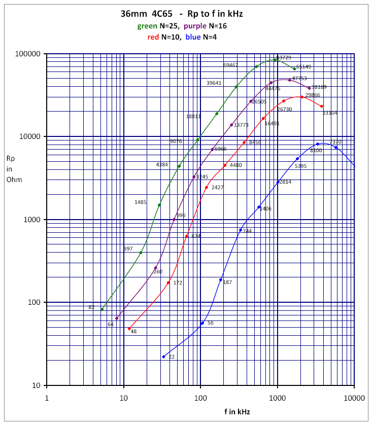
Preview multi-winding test 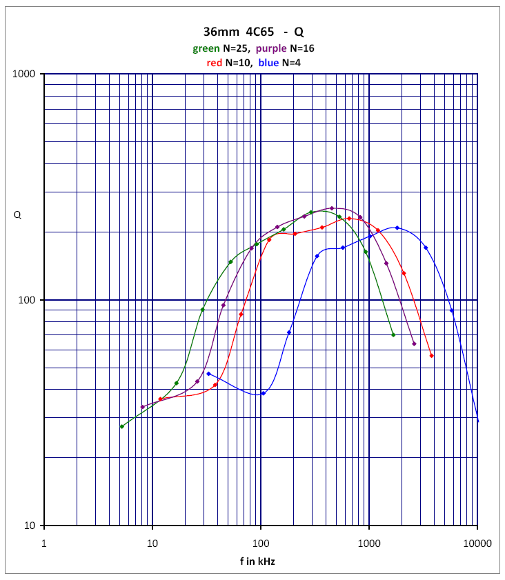
Material survey Ferrites 
↑ Survey PDF 
↑ 3C11 - WHITE 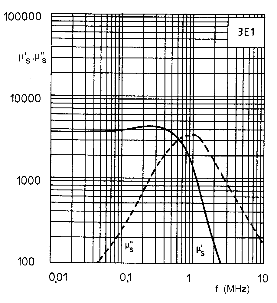
↑ Old 3E1 - GREEN 
↑ 3E25 - ORANGE 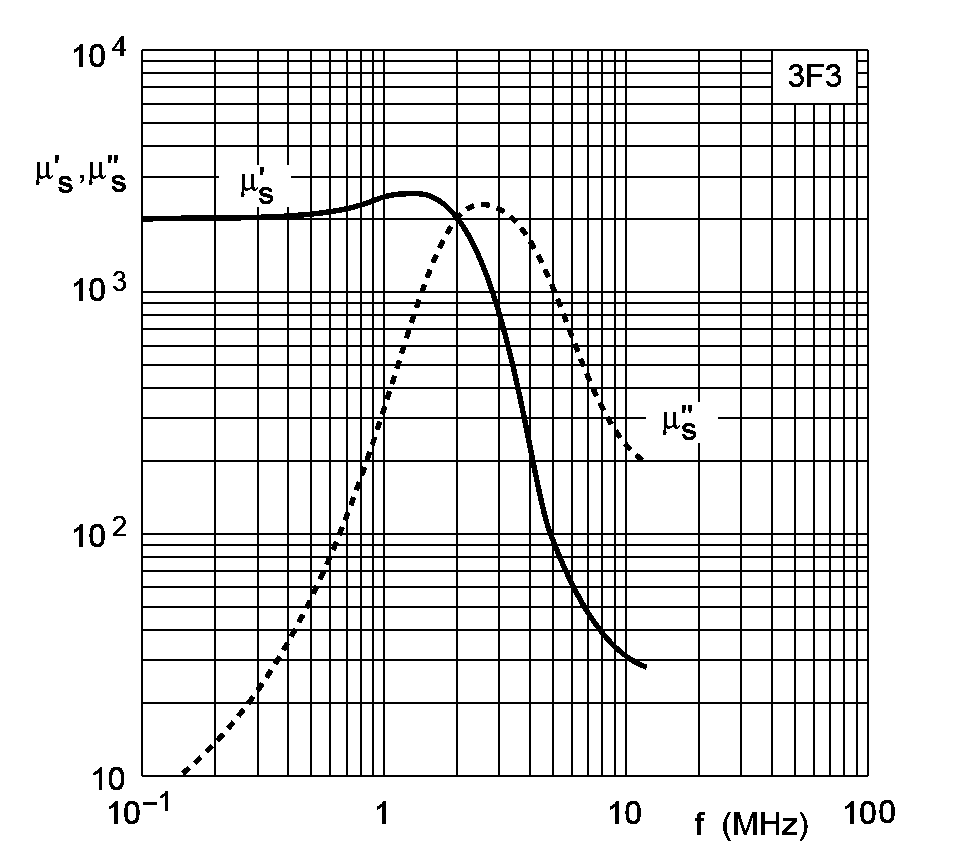
↑ 3F3 - DARKBLUE 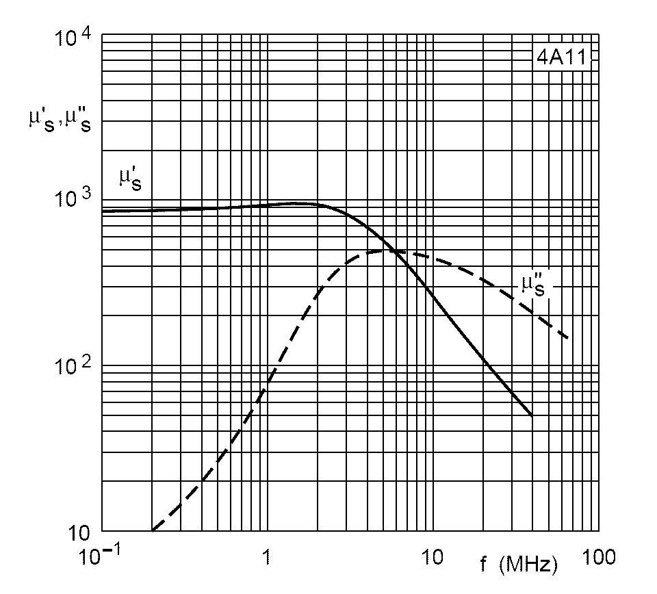
↑ 4A11 - ROSE 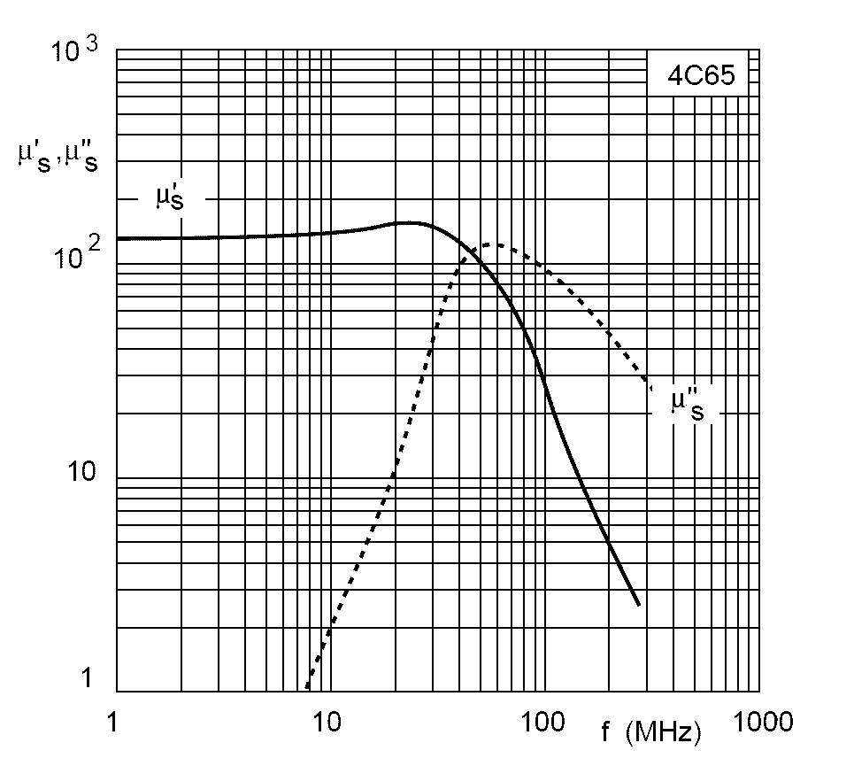
↑ 4C6 of 4C65 - PURPLE 
Micrometals Powder iron ↑ Txxx-2 loss curve page |
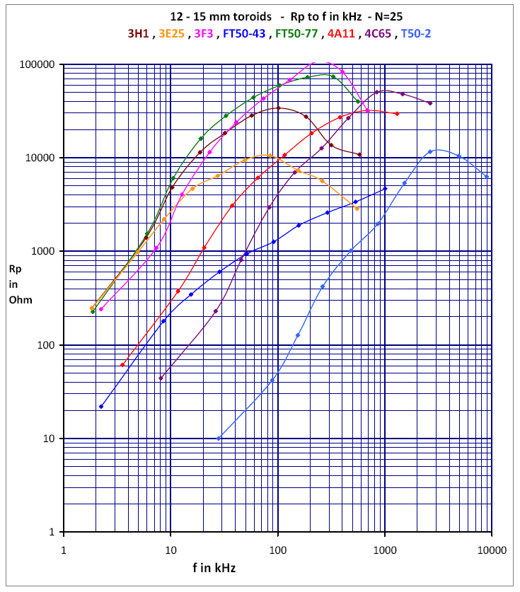
Here, an explanation of what is calculated from the measurements and some conclusions that have emerged. Each multi curve set may contain hundreds of measurements! Only with a long look at the many curves the effects are becoming apparent now. Some of the Ferricalc measurement sets together with charts are downloadable as PDF. All measurement data are processed with the latest version of my program Ferricalc.exe. The *. CSV results are again processed in Excel for the graphic presentation. There are curves made for variations in the measurement results and they are expressed in Rs, Rp, Q and AL. What are these things and what do you see in the curves? After thousands of measurements have shown: (Rp for all toroids with N=10) Toroids with the highest Rp, 10,000 to above 100,000, are ideal cores for low-loss MLB applications. Preferably for the low frequency portion use 3F3 (once dark blue), Magnetics F material, eg. ZF-42212-TC, or FTxx-77 cores. The old 3H1 (red and yellow) scores also not bad. Use them in combination with 4A11 (once rose), FTxx-61, HF40 from TDK or 4C65 (once violet) for the high frequency part. Cores with a proper initial value for Rp, but which remains much lower between 1,000 and 10,000, and having a significant LOSS part, are ideal cores for damping and suppression applications. So for common mode current (Guanella) baluns and EMC applications. Low-f 3E25 (once orange) and 3C11 (once white), for higher-f 4A11 (once rose) is usable and FTxx-43. You can still use them for a MLB, but with a (much) larger absorption. Therefore NOT preferred for Tx as a "voltage" balun. First, a little explanation of the above units, Rs, Rp, Q and AL. Rs Rs is the conversion of ALL losses (characterized by a particular measured Q) to an equivalent (frequency-dependent!) series loss (coil) resistance.
However: at low values below 1 ohm a large part of Rs is formed by the used calibration capacitor losses and not by the coil. Sometimes, a very large proportion is by the C. The lower part of the graph is therefore a good test to see if the C is "sound" in the measuring module. The coil Rs result in the lower part is not really in the picture. Only after doing this type of measurements and conversion of the data to Rs some failures (in C of the measurement modules) have emerged! UPDATE: after the purchase of a Mastech MS5308 LCR Meter and also the construction of the Elektor microprocessor RCL meter it is now possible to measure the dissipation factor D of capacitors up to 3 digits after the decimal point (= up to 1 per mille). Above 2 permille at 1 kHz (D = 0.002) is already asking for difficulties. The 3 modules with the largest C values (350 nF, 1000 and 10000 nF) are NOT OK. They have been rebuilt. This gives a much better Rs curve in the low! However, not many capacitors meet this requirement! The WIMA FKP series, however, has D values below 1 per mille. Even at 10 kHz! It is therefore strongly recommended, especially for ALL modules above 33 nF, to put at least 10 C's in parallel with one tenth of the wanted value. These capacitors are previously selected again from an earlier test where they had the lowest Rs value. Wound (rolled) professional (dump) 1% calibration film capacitors were found to be precisely the worst in the Rs measurement. A little further an image is inserted of such a rolled C, or already click. Modern film capacitors with the shortest possible dielectric connection is therefore recommended. Precisely do NOT use ceramic C-materials, they have an extreme temperature dependence. However, they do provide better Rs values than with foil C's (!), but, as said, have a hughe temperature run-away. For very small values, mica is the best choice. The best types of mica 0.5% (up to 100 nF!) I salvaged from boards of a 50 year old 300 baud modem with potcores (and punch tape interface .....). On pictures on this site they are the flat brown "blocks". Only above 1 to 5 ohms equivalent series-R, the Rs values are mainly determined by the self-induction on the toroid. Also Rs is running high non-linear with frequency. Rp With Rp ALL the loss effects (characterized by a particular measured Q) are converted to an equivalent (frequency dependent!) parallel resistance.
With the rise of the frequency this gives an increasing Rp, however, only obvious to a certain maximum. Then, from this point, Rp GOES DOWN by the damping of the LC-circuit by the increase of the frequency dependent loss effects, they apparently are getting bigger and bigger! QB√2 (Q at the -3 dB f-res points)
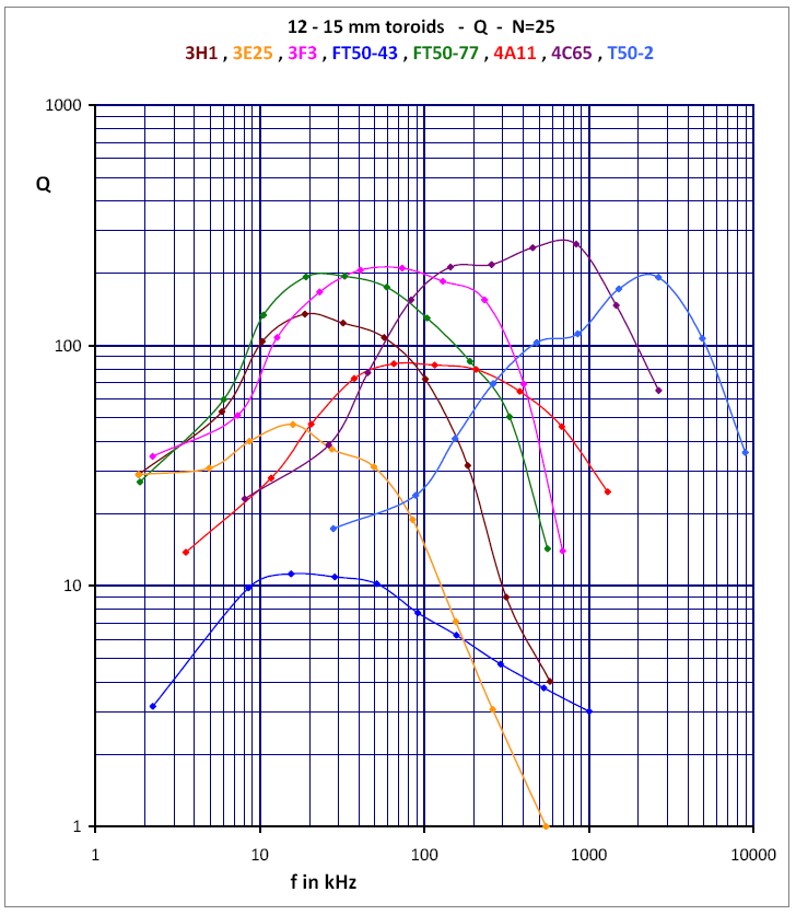
In the Q graphs, the maximum achievable Q, limited by the losses, is represented. Here too, Q first goes up with the frequency and then drops again. Put it next to the Rp curves and see the maximum goes up (and down) just a little different as with Rp! In the Q (and its derivatives ...) by the above measuring method are automatically tolerances, which always rise higher in larger Q. Why? When estimating and reading off the -3 dB f-res points (QB√2) there is a certain inaccuracy. This percentage is not too bad, but keep in mind the absolute variation. We subtract two such values from each other. At high Q the delta-f result is getting smaller and smaller / thinner. The error values are now TWO absolute tolerances added together. In percentage of the subtraction it can easily make 10% or more. In a Q above 100 therefore a 4 digit counter figure is not accurate enough, 5 digits is better! With a little run-away during the measurement it is imprecise at least another such value, closely measure (and fast!) is rather difficult ..... That's why I had to do some measurements for bumps or sags in the Q curve again! Sometimes you see that therefore still! There is also an additional loss angle tan  problem of the C to be designated as the second cause of a possible dip, more later. problem of the C to be designated as the second cause of a possible dip, more later.
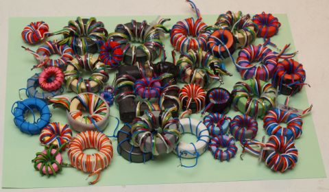
AL Here you can see the relative inductance value of a specific toroid expressed in the AL value. I've calculated them from the resonance data obtained with the TOP-C method. The default AL value is expressed in nH/turn, equals mH per 1000 turns. A formula in HTML is too difficult, I'm pasting therefore an image: 
You do not have to type your fingers cripple on a calculator or afterwards in Excel anymore, download therefore the compute and documentation software FERRICALC. Two co-operating modules in one EXE. The ZIP file contains an EXE including examples and PostScript overlay files. How do I do the juggling with the formula above? Much more additional (older) information concerning the measurements, the formulas and the Q correction factors in a separate PDF document, an extract from the old "Ferrite Info". click here for that particular document in PDF. Oops, it is still in Dutch ... For some (high AL) values extremely variable, for lower values just returned relatively stable and not be so frequency dependent. Because the higher AL values are much more sensitive to saturation effects, incurring AL and then again greatly sag to nil at even higher frequency and even more "lapse" by temperature effects, these curves are sometimes quite fickle. Re-measurement can easily yield a variation by 5% AL inaccuracy due the lapse! (And the Q does 10-20%). Different exactly the same toroids can yield 15 - 20% AL variation. Partly due to the fact that at a higher Q, by subtracting the two nearby f-res points from each results in a small value, resulting in a relatively large percentage of deviation therein. (see Q for explanation) Also the number of turns has a small/limited effect on the AL with the method followed. For winding effect tests (N=4, 10, 16 and 25. N=36 is not done yet) material is used with the greatest frequency bandwidth = (ex Philips purple) 4C65. Usually the 36 mm version. When a core with only few turns stays somewhat blank (bare core spots) it is wound with many multiple threads in parallel to ensure good core coverage and this gives a lower leakage inductance. For mutual testing and comparison of various manufacturers 12 to 15 mm cores were chosen because of their availability, done with N=10 and N=25. In addition to ferrite is also the red powder iron variant included (T50-2) for comparison. Later a test set with toroids between 20 and 28 mm with N=10 added. Ferrite material from Fair-Rite (= Amidon sales circuit) showed extreme saturation and temperature sensitive, a.o. measured at FTxx-77 and FTxx-43. Philips (rose) 4A11, comparable and sometimes much better material than FTxx-43, precisely not. Although: subsequent measurements with Philips 3F3 gives exactly the same picture. This 3F3 material appears again as two drops of water on FTxxx-77! Probably combines in this case (3F3 and FTxxx-77) low-loss NOT with a low temperature coefficient. |

↑ Fair_Rite / Amidon 77 material comparable to ex-Philips 3F3 blue |

↑ Fair_Rite / Amidon 43 material comparable to ex-Philips 4A11 pink |

↑ Fair_Rite / Amidon 61 material comparable to ex-Philips 4C65 violet |
| Software set from PE1ABR to calculate and document it all fast and neat |
|
|
The A5 TOROID CORE fill-in sheet programmed in postscript - 2x in one A4 PDF. Latest version is 5mm smaller, so hopefully no longer scaling is necessary to print the PDF. |
|
|
A graphically stretched version (from a converted TIF) from the UK A5 TOROID CORE fill-in sheet with more lines for at least 20 measurements in draft on one A4 sheet to write it all down during the measurements. Due to TIF conversion something lower resolution. |
|
XP snout WIN7 snout (Dutch) Linux snout Two example PDF's |
The piece of software - 3rd highly customized version - compilation run_56 of FERRICALC.EXE . Extract ZIP content somewhere in a folder together with RINGBLAD3.ps and all the other files from the ZIP. Many additional features added, Dutch as wel as English help files and *.ps versions. Further more idiot-proof! This version has a reasonable snout under WIN-7 by using scalable new "Open Type" fonts were previous "True Type" were used. This version 3 of the program actually consists of TWO separate window sections (and EXE's), the original (extended) arithmetic section, and the postscript fill-in sheet. The latter program has not been on the site .... The calculation program patches the data on a selected fill-in line in the second window. There is space for 7 measurement lines. In this second window the info can be edited as you want it. You can now save, retrieve and / or merge of own *.TOR files. It can also be done in "Notepad" or "Notepad++". When completed the export takes place to a postscript file. Or also to an Excel *.CSV, in it mainly the measuring data. Filling in the data in the print file is done as an EPS overlay in this RINGBLAD3.ps postscript file. You have to rename the English version to this internal name. Through a Save_As dialogue the print file can be stored with a self-selected *.PS name. The PDF printing is sharp, keep the printed sheets in a documentation folder! The ZIP file left has a.o. the EXE and the PS file. It also works under the WINE emulator on Linux. A fast preview of the *.PS files, before they are converted to PDF, goes best with Irfan version 4.28 (only from this version and up!) that works together with a special Ghostscript plug-in. It makes a low-res TIF that gives a fast first check to see if all is OK. But it doesn't give a sharp printout. As a workaround you can adjust the Ghostscript DPI values to a higher setting. If you use a later Irfan version be sure the Ghostscript plugin is available and installed. Converting the patched *.PS files to *.PDF also goes online via http://www.ps2pdf.com/convert.htm of via http://www.stuffedcow.net/ps2pdf or you do it "locally" with Acrobat Professional or Distiller or with a similar program. |
|
Window Image |
With extensive measurements everything does not fit anymore on one A5 sheet. Recently a PostScript merge program has been created, drag 2x an A5 (in Top and Bottom field) and save as a new *_Combi.PS file in A4 format. PostScript adjustments in both files are applied together with a postscript coupler. It also works on Linux / Wine. Through special %%Box-params the Ghostscript pre-view looks identical under Windows and Linux. Due to a Ghostview bug (?) at first it was NOT! Although the Adobe PDF was quite OK! |
|
RUNTIME__vb6 Winhlp32 XP Winhlp32 32b script Winhlp32 64b script |
In standard Windows2000 and also in a bare XP (and also in a bare Vista and W7, and of course in windows 10 too) lack the VB6 runtime and OCX library (COMDLG32.OCX and msstdfmt.dll). You can also get them here. In 32bit systems put the files in the C:\Windows\system32 folder, in 64bits system in C:\Windows\sysWOW64, and register the files, this usually goes OK with corresponding batch. Possibly in newer Windows versions only with the option "Run as Admin". In 64 bit systems it is convenient to run the 32 bit batch ALSO, then the files are in both system folders. Also with WINE it works fine under Linux. Put under .WINE in the folder ../Windows/system32 place the help files and register them in a Terminal screen. Even the VB6 .HLP files work with Windows10 with the help from this link That was apparently too nice, because the path to the source files there has been destroyed, the explanation is still fine. Fortunately I had spare copies and I made ready-made custom CMDs with WINHLP32.EXE installation files for 64 bit and 32 bit Windows 7, 8 and 10. Sitting under the links are ZIP files. Put the correct zip content in a ROOT folder C:\HELP\ or D:\HELP\ and start the *.CMD as Administrator. UPDATE: The 64-bit Windows-7 or 8 version of WINHLP32.EXE does NOT always gives a good result in Windows 10-64bit. No more dummy info, but also no "help" start up. The 32 bit (XP) version DOES give a good result (also in 64bit W10 !!!), and also with Ferricalc (and other old software) under W10-64. In desperation I replaced the winhlp32.exe in the zippers above with the XP version. Finally everything OK after running the scripts (as admin)!!!! After a heavy W10 update it is possible that the old help function is "fucked up" again. Run both! scripts one more time and it works again. To be on the safe side, I renamed the dummy EXE beforehand. |
|
The measurement results and charts are all set ready as PDF on my server. Patience! For a multi-multi-test the PDF's are for ease of use together in one zip. |
Preview multi material test with N=25 Click for much larger version! |
Preview multi material test with N=25 Click for much larger version! |
|
 From which measurements you will find in the left column a PDF? Multi N tests with 36 mm 4C65, N=4, 10, 16 and 25. multi material tests with N=10. 3H1, 3E25, FT50-43, FT50-77, 3F3, 4A11, 4C65 and T50-2. Because of availability with toroids of 12 - 15 mm. For comparison: powdered iron test T50-2 added! The small FT50-43 appears to be a very bad one. multi material tests with N=25. 3H1, 3E25, FT50-43, FT50-77, 3F3, 4A11, 4C65 and T50-2. Because of availability with toroids of 12 - 15 mm. In the column left a preview ... For comparison: powdered iron test T50-2 added! Once again: The small FT50-43 in this test turns out to be a very bad one. It should be comparable with the 4A11, but what I have is a flop. The FT50-43 is certainly a factor of 10 worse in the loss curve than "similar" 4A11. Afterwards even larger FT82-43 and FT82-77 were tested. Here the -43 is found to be comparable (and sometimes just better) than the 4A11, but now the -77 is much worse than 3F3 The AL of the Fair-Rite material is correct, but the loss curves are extremely unreliable! At least NOT stable / reliable. Unsorted still 100 toroidal test variations available, but it could be something too much ....... A few have I added. Among others a combined curve set with FT82-43 compared to 23 mm 4A11. See the separate cores for the measuring sheets. Some preliminary conclusions and remarkable things as "loose slogans" listed here: In the Q curve after the maximum, the "bump", pretty soon a declining trend is seen. When, however, still an increasing trend is present in the Rp curve, it is still possible to use it in a LC circuit (with moderate Q), e.g., to the point that there the maximum is reached. This appears neatly in line with earlier "guesswork", that is, keep the loss curve part below maximum 7.5% of the manufacturer's mu curve. (see main ferrite page) For transformer application no problem yet. After the maximum of Rp, the Q has become too low for LC application and the loss prevailed as a low parallel ballast or damp-R. That is for resonance application unusable. Depending on the application (only transformer with local low Z, no f-res, and very small magnitude of power) shall demonstrate if the core material choice and if the number of turns is still OK. At least it gives an indication of power problems which might be expected. C limitations at low frequencies In the Rs curves in the lower left corner, e.g. below 1 ohm, more can be seen on the used capacitor quality than about the coil losses. Professional (older) 1 or 0.5% film capacitors with standard wire connections are here "own up"! These Cap's are the well-known large rolls such as the Cap top left of the picture on the right. 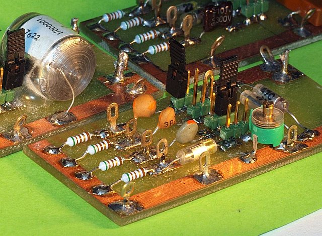
Modern film C's have the metalfilm stick out on both sides which makes contact (with extremely low Z) with the terminals. You can see this well in the older "naked" MKH / MKM / MMK capacitor cubes. Only in this way you have a very low parasitic L and higher resonance frequency. Use this information, as previously noted in the description of Rs, to select the right measuring C with the lowest Rs by doing some tests with the same coil with e.g. max N=10. I did it with much less: N=4 with 10 wires in parallel! Take therefore low AL 4C65 material with low loss. Then afterwards put 10x a selected good C parallel for a excellent module with total C-value = 10x C. (and the parasitic Z is thus (hopefully) 10x! in parallel) See the first PDF's adjacent (left). C limitations at higher frequencies Low AL NiZn toroids with an associated high Q, have possibly in the top of the Q curve dips or bumps. The Q curve is no longer a smooth line to the top. A module with only one mica C was most affected, i.e., having only 1 Cap. was the cause of the dip. It turns out that also the lower C-values are better off with several good film or mica capacitors in parallel. Then, a high-Q above 200 is more accessible, because it also depends in turn on the quality (tan ) of the measuring-C!Thus, in the top of a Q-measurement curve, a dip? Better testing of the measurement Cap. recommended! In previous measurements, this was the case with the Cap. of 10 nF (10670 pF) module. You can see the dip in the Q curve in the 12-15 mm multi-toroid tests. The new (multi-C) 10 nF Cap. is about 10620 pF. Material with the highest Rs value and at the same time a low Rp, which as well as by running far in frequency, is the ideal absorption EMC material. In the N=10 and N=25 compilation graph/ curves that is with the toroids 3E25 and a (bad) FT50-43. More from the N=10 and N=25 test: Material for the best broadband transformer application should just score as low as possible with Rs. In the Rp curves (and Q) again can be seen how far the Z can rise and up to which frequency. A pair of low-AL and high AL toroids who score both the highest in Rp are the ideal low-loss combination set for a MLB!!! This is apparently not the 3E25 for the low as I myself have used a lot, but apparently the FT50-77 (and afterwards tested: 3F3 also is perfect, and many more unexpected that I had in stock). So: The duo toroid application for MLB is better off with the FTxxx-77 (or 3F3) and 4C65 (or FTxxx-61 or TDK HF40 clone), than with the 3E25 and 4C65 set. Rather a size larger than FT50 (21 - 28 mm is ideal), so better use the FT82. Two low AL on the outside and one high AL in the middle (so 3 toroids together) shows the lowest leakage inductance and the largest bandwidth. When the high-AL material begins to lose its effect, it should not be on the outside ==> that gives additional leakage L. The 3E25 orange is perhaps just a too heavy ballast load with MLB dual-core use. If we just do not use the 3E25, unfortunately the frequency range on the low side goes less far into the low. And more turns are not good either for the high frequency range. For common mode application and anti-EMC just fine again! It also appears that the taken out of production material 3H1 from Philips does not score unkind, previous measurements already pointed in that direction. Good low-loss stuff. There is almost no difference with the loose sold quite fragile MLB core from Kent Electronics from the '90s. Is it still available? 3F3 (dark blue), see below, has a lower AL and hence scores in the high-f even slightly better! To be added: comparative tests with 23 mm 3C11 (white), if I can find them .... Note also the place that the powdered iron curve (T50-2) has been given. from the N=25 curveset for Rs, with 12 - 15 mm toroids 4A11 choice in favor of FT50-43 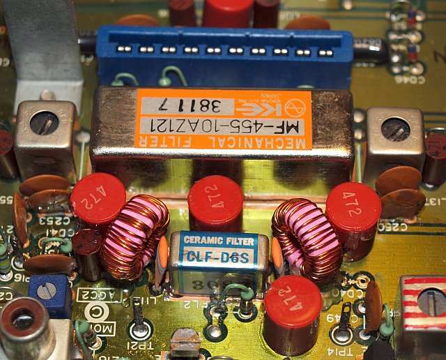
(Z test with N=25, in reality about 30-35 turns are required for the needed 330uH ...., I've tested it in a JRC NRD-515 with excellent results, 20 to 30dB better far-suppression.) The so-called equivalent Rs of the FT50-43 toroid is already above 200 ohms! The comparable parallel ballast in the Rp curves: 4A11 parallel loss Z = 30 kOhm. The FT50-43 scores just above 3 kOhm. Even though it is used in a low-Q 2000 ohms 455 kHz filter circuit FT50-43 is still not a convenient choice. I already knew this from previous separate measurements for use in the NRD-515, but now you see it graphically. The FT50-77 (or 3F3) might also be just, but the 3E25 on 455 kHz (for an LC circuit) is an even worse choice than the FT50-43! Both FT50 variants have a much higher temperature runaway than 4A11. They are also much more sensitive to saturation effects, even at 100-200 mVtt! (= 35-70 mV rms) For EMC and Guanella (common mode application) is FT50-43 fine (like 4A11), but for LC circuits, even at low f very discouraged! Compare in the material curves the dotted losses curves at the top of this web page for FTxx-43 and 23mm 4A11. Then you see that they should be similar. At "77" material and 3F3 you see the same similarity. A test with FT82-43 gave a completely different result when compared to 4A11. They are comparable. Apparently no stable (loss curve) production results from Fair-Rite (sales through Amidon) vs. Philips? It is also possible that my deviant (bad FT50-43) toroids are from an earlier production date. I found this on the site of Clifton Laboratories One has the "formula" of the composition of "43" sometimes adjusted (perhaps copied the composition "formula" from Philips?)! It must therefore have been known by Fair-Rite that "-43" was not perfect at all and very lossy in the past. What do I see in the multi-N tests with 36mm 4C65? The Q curves for N = 10, N = 16 and N = 25 depart not very much from each other, they have the same shape. It shifts only a little along the Z line and frequency. Apparently, the Q effect is more dependent on the type of core material, and AL than the number of turns. Although N = 4 or somewhat different. In Rp the bump just shifts a small amount forward. After the addition of the test with 14 mm 3F3 (with N = 10 and N = 25), there appears to be something special! The sensitivity to saturation effects at low f, and the huge temperature dependence (even a grab: always a small shift), is almost the same as the FT50-77. The materials have a speaking similarity. It can not be more clearer than in the curves! So for stable resonance and LC filter networks therefore not ideal, but for broadband transformer application all the more. Hence MLB! Also in combination with 4C65. 3F3 material has a slightly lower AL than FTxxx-77. Hence with the same N a slightly higher "start-f", and a little further in the ongoing high. But that makes little difference. Conclusion: This Ferroxcube (ex-Philips) 3F3 type of material is the almost exact equivalent of the Fair-Rite (sourcing Amidon) FTxxx-77 ferrite mix. Biggest problem: who supplies 23 / 25 mm 3F3? TME Electronics - Poland! Ferroxcube PDF info 25mm 3F3 version. The above hit upon the idea: special low loss MnZn material is also automatically less temperature stable. In other words a low-loss value and a low temperature coefficient does not go together? |
| A selection of the links from the Dutch language version page Some documents are in English, some have Dutch language. They belong as extra documentation to a "Ferrite" presentation/lecture I've given. |
|
|
Latest material info from the Philips / Ferroxcube / Yageo databooks. |
|
|
A historical overview of the Philips 1973 Soft Ferrite databook CM4a__10-73. The delivery program and the toroidal variations of those days. Important for all older core types e.g. the purple 4C6, green 3E1 or (yellow/red) 3H1 cores or those from the dump. |
|
|
A set of old Amidon scans. |
|
|
The Micrometals part put with Amidon. Source of the powder Iron cores. |
|
|
Extract from the Fair-Rite book - equals the ferrite from Amidon. Also a nice story as starter. |
|
|
Material info from the Neosid databook. |
|
|
The table with the Z of interference suppression and RF coils - 4th version. To get an impression of realistic coil values for a given frequency, text and decimals in Dutch. |
|
|
The table with mainly the Z and associated leakage current of 230V mains capacitors - new version 2, text and decimals in Dutch. |
|
|
The table with the Z of HF decoupling and coupling capacitors at a given frequency - new 3rd version. Realistic and NON realistic component values, text and decimals in Dutch. |
|
|
The A5 TOROID CORE fill-in sheet programmed in postscript - 2x in one A4 PDF. Latest version is 5mm smaller, so hopefully no longer scaling is necessary to print the PDF. |
|
|
The English version of the application of the Elektor Coil meter with a smart coil cord. |
|
|
The French version of the application of the Elektor Coil meter with a smart coil cord. |
|
|
The German version of the application of the Elektor Coil meter with a smart coil cord. |
|
|
The Dutch version of the application of the Elektor Coil meter with a smart coil cord. |
| A handy set of comparison lists from multiple ferrite manufacturers |
|
|
The handy ferrite Cross_Ref_List from Iskra Feriti, new version |
|
|
The handy ferrite Cross_Ref_List from Iskra Feriti, old original, but with some error correction from PE1ABR. |
|
|
The Cross_Ref_List from ACME, version 1. |
|
|
The Cross_Ref_List from ACME, version 2. |
|
|
The Cross_Ref_List from DMEGC China. |
|
|
The Cross_Ref_List from KOLEKTOR. |
|
|
The Cross_Ref_List from MMG India. |
|
|
The Cross_Ref_List from TDG. |
|
|
The Cross_Ref_List from YENG TAT. |
|
|
The overview table from the famous book Soft Ferrites from Snelling - historical manufacturers list from 1969. |
|
|
The overview table from the second version Soft Ferrites from Snelling - this historical list is from 1988. |
|
Back to the Ferrite page with technical background information or Back to the Ferrite page with manufacturers table or Back to the Inductor page with suppliers and components or Back to Quick menu at the HOME page or to the top of |

|
|
|
Dutch? |
| ferrite losstest info -- losstest_UK.htm by Walter - PE1ABR - 2024-03-04 |