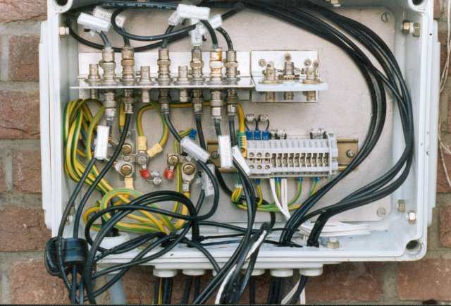
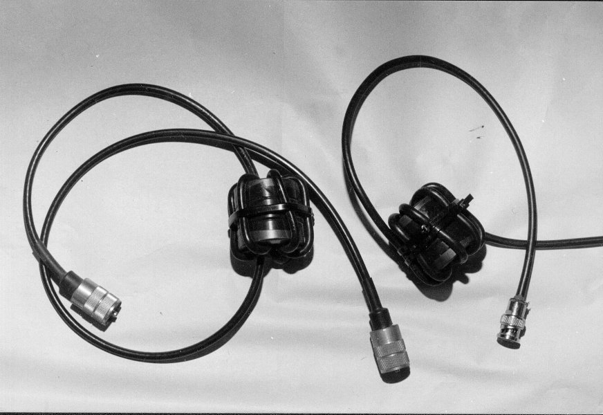
Wall mounted cable box.
Without mains short circuit bypass, so with dual earth, local and HF separated - not adviced.
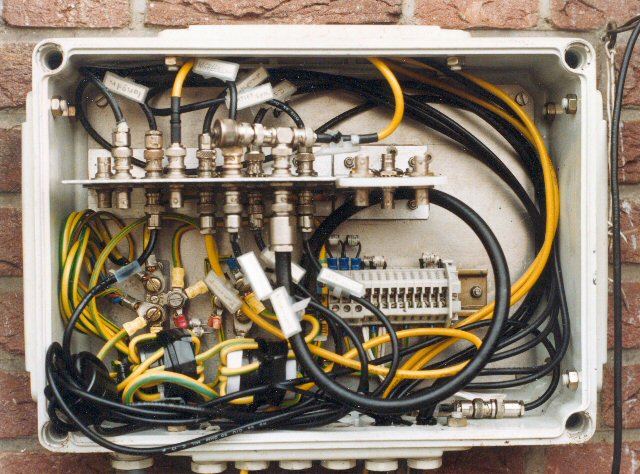
Wall mounted cable box.
Still dual earth, but with added mains-current short circuit bypass HF-coil set.
Adviced !
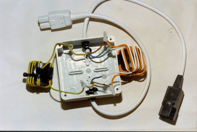
Add-on mains filter with separate earth coil, for bad computer PSU's and wrong designed monitors.
exploded view.
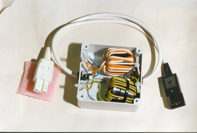
Add-on mains filter with separate earth coil, for bad computer PSU's and monitors.
2x 3 toroids: 38x18,8x12,7 mm
type F ferrite
NO coating,
Magnetics 43813-TC
Use at least 10 windings

VLF/ longwave/ medium wave common mode suppressor for an active aerial high in a dead tree. Isolating the coax from the aerial.
4x a 3C11 clone from Ali with lots of thin teflon coax
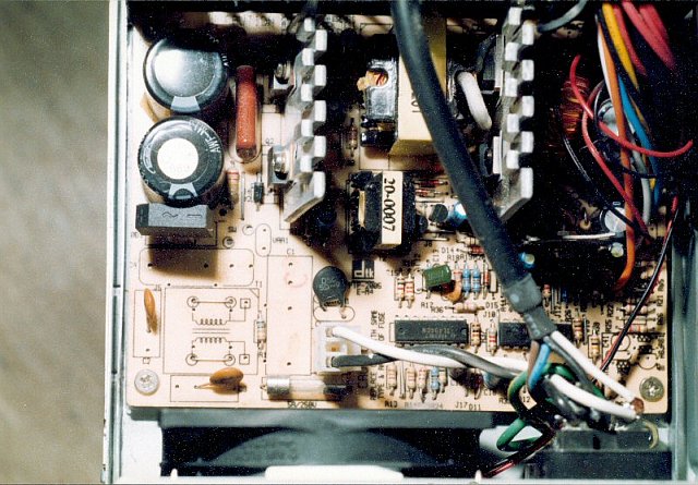
EMC/CE violation
NO mains filter at all!
completely left out to reduce costs!!
Result is heavy growling from VLF to above the medium wave
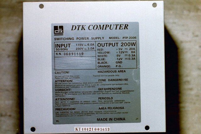
And this is the EMC/CE violating factory......
How to make a VLF/HF common mode suppressor.
2x 3 toroids: 38x18,8x12,7 mm
type F ferrite,
NO coating,
Magnetics 43813-TC
AL value > 5300 per toroid core

Another VLF to low HF common mode suppressor on the roof for an active aerial.
Lots of thin teflon coax windings, so optimized for low frequencies.

BAD adapter circuit modified and in a larger box
After the in- and output coils an extra C is added, directly over the wires going out of the box
Mains extra = 47 nF - X2
+5V extra = 47 or 100 nF 100V
L - 3E5 = +/- 3.6 mH
L - FX1000 = +/- 2.3 mH
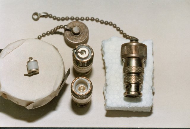
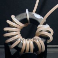
How to make an arrestor for direct mounting in the coax.
Connect with a T-junction, see second photo on top in cable box.
picture © PG9HF
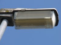
HF lamp-post with EMC problems.
Inside is wrapped in copper shielding mesh.
PDF article in DUTCH by PG9HF and PE1ABR
Click on picture © PG9HF
Electric fence immunisation.
PDF article in DUTCH by PG9HF and PE1ABR
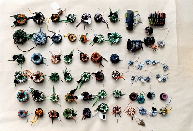
Many ferrite transformers made for a hughe transfer test.
Tested are different materials and winding methods for as large as possible usable bandwith

BAD adapter circuit modified and in a larger box
On board added:
mains 100nF X2, after 10 Ohm R. Trace to R is cut,
Cap is over AC bridge terminals
+5V extra = 47 or 100nF 100V.
The deleted 470pF Y2 is also added again