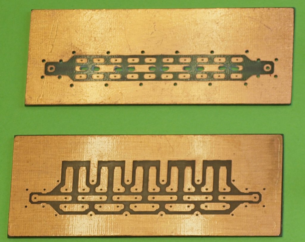
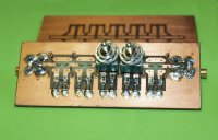
The board twice,
to see top and bottom.
The choosen coax connectors are SMB, something else is too awkward/clumsy.
If you mount this device in a small table-box, you can use BNC over there.
The set with the CAD layout files in one PDF.
|
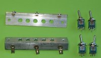
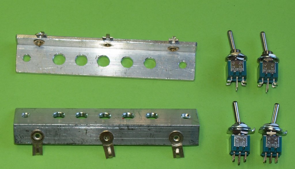
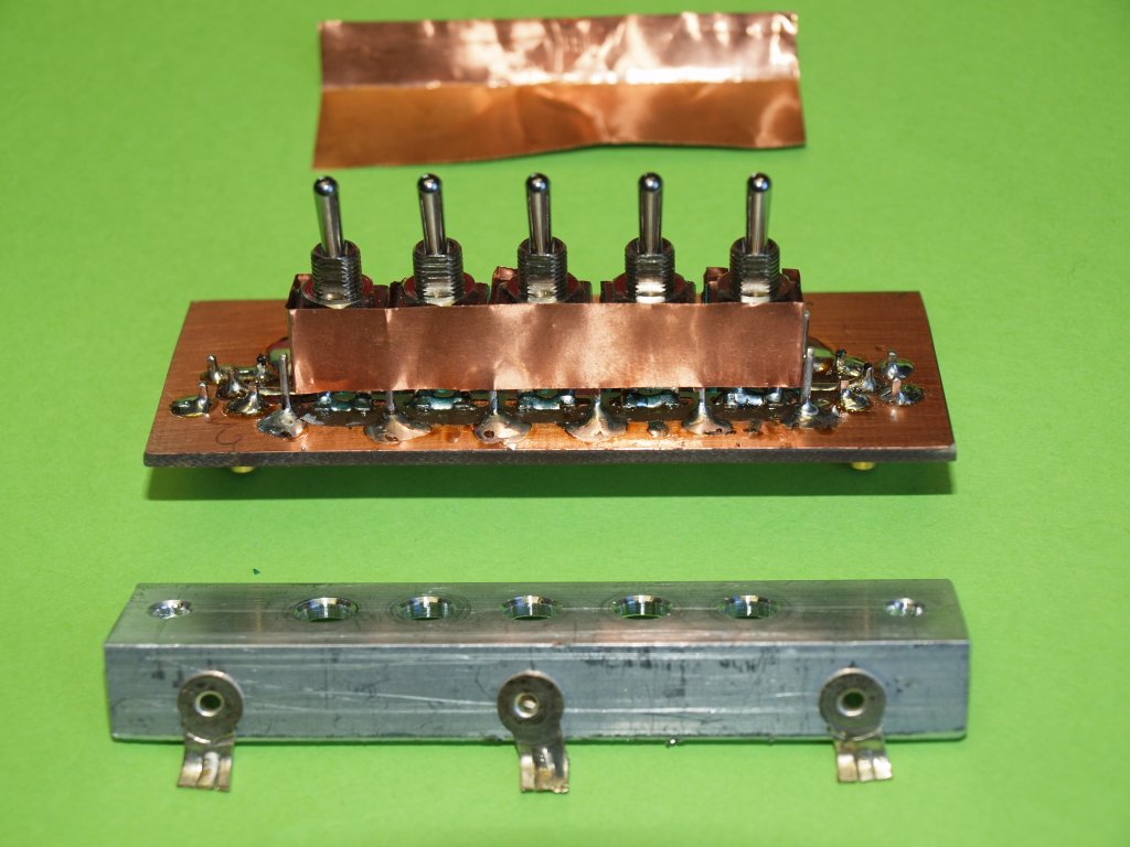
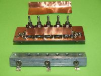
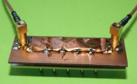
The special bracket, twice.
It is 10 x 10 mm alu strip with solder lugs.
They are rivited in place.
Be very carefull when drilling the holes.
You also see some of the tiny switches that need to be modified.
The outer four lugs are bend outside.
|
Start with the SMD R's, for 10 dB networks 2x 100 Ohm and 1x 68 Ohm will do ( and are available!!)
Press the 1 mm poles in place and solder the Coax connector, top and bottom.
Bend the poles to the inside.
The switches should fit between 4 poles.
There should also be room for a shim of copper foil. If needed file the poles.
|

Try to put all the switches in place, but do NOT solder them yet!
Mount the bracket, bend the solder lugs a little on the bracket.
Place and remove the bracket a few times to see if all the switches are in the correct position and the bend lugs of them are all touching the board. Lower switch nuts are against the switches.
And for clearness: the inner lugs are going through a tiny slit to the back.
|
If all is OK, then solder the outer lugs on top and the inner lugs on the bottom.
The coax input and output inner switch-lug in contrary also on the top side.
REMOVE the bracket carefully, don't brake the soldered switches.
Correct the switch solder if needed! Don't let them come loose!
Put small pieces of copper shim plates between the switches - don't make short circuit with the solder.
|
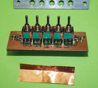
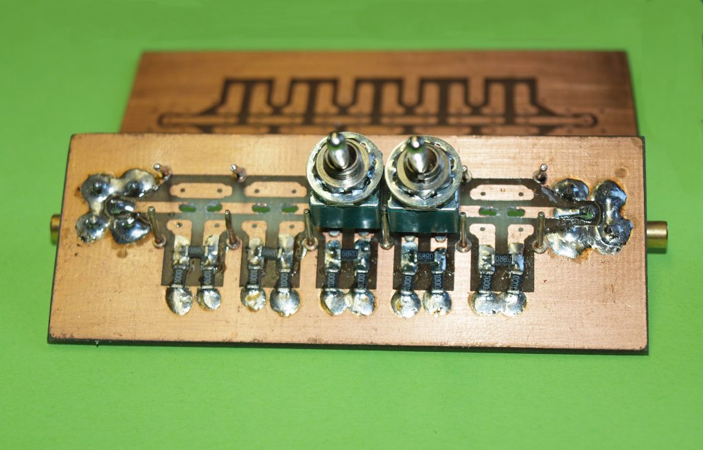
The foil shim should not be in the way for the bracket.
Finally put a long foil shim on the complete back and let it go to both front sides.
Here you see it from the front (with resistors) how to do it.
The final cover foil shim is ready to be placed!
To avoid breaking loose on the back, you could strenghten the copper traces with small pieces of wire.
|
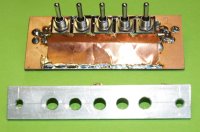
At last, that's in place!
Try to solder all the connections between the foil shim plates.
BE A PLUMBER....
|
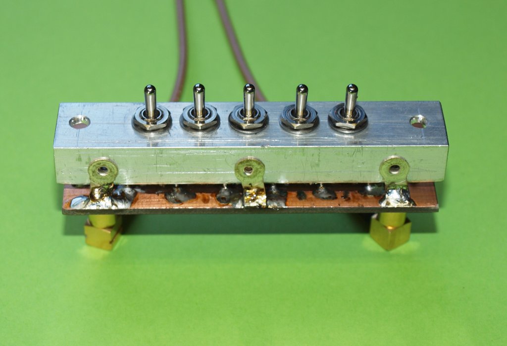
Carefully put the bracket back.
Don't brake the switches during fastening.
Solder the bracket solder lugs to fix things....
|
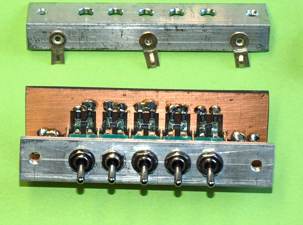
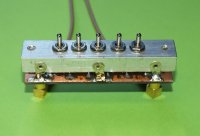
On the back it has to be screened/covered too!
And this is how it looks over there!
How it works?? You will be amazed how neat the -10 dB steps work!!
Especially compared to a version with standard resistors if you ever build one.
|