
A collection of even more  diagrams and modifications |
Handwritten code made with EditPlus
|
|
|
| Links to more | information: |
|
Most of the PDF diagram information is already on the internet, but in versions I dislike. Too low resolution (like 200 DPI), too much grey or unneeded 16 million colors information, much too low contrast, or with nasty stains. PDF's over here are optimised where possible, cleaned and edited or combined versions from multiple sources. And with additional repair, update and alignment info. |
| Item | Highres TIF in PDF file |
Highly edited version of the NSD-515 (transmitter) user manual. The brother of the NRD-515 receiver. Almost the same cabinet, almost the same knobs on the front. They form a DX duo. The NSD-515 is a "transmit only" device! NO Rx function! Made from a PDF from the web, unfortunately much too low 200 DPI (3 times too low) scan in 16 million colors, and also with too low contrast ratio, scanned by GW8ARR. All is better than nothing at all, thanks, but it took me many days to upgrade it completely. My version is bilinear converted from 200 to 400 DPI TIFF with linear intermediate pixels. Then 2 stage histogram correction and Black-White maximization. To avoid "torn-out" characters I didn't convert them in a last step to 2 colors, but to 16. It gives a smoother character image. If a picture is on a page the text version is converted back from 16 colors to 256-grey (with ultimate black-white now) and the separate upgraded picture (also in 256-grey) is pasted over the muddy black one. Almost all pages were saved in TIFF-LZW. My edit version is better for print, you can click the original for on-screen if you like. |

Moving GIF 
original edit |
Highly edited version of the NBD-515 user manual. The NBD-515 is the exclusive power supply unit for the NSD-515 transmitter, the item above. Just like above made from a very bad 200DPI scan in 16 million colors by GW8ARR and the images and drawings here were that bad that they are from the Japanese version PDF that was original in 400 DPI - 16M. This version here is in text mode bilinear converted to 400 DPI 2 color TIFF (like above) and pages with a picture via 2-color text after adding the pictures from the JP version to 256 grey in LZW-TIFF. Optimized for printing. Compare with the original if you like..... Remark: The supply is NOT a very good design, compared to later versions below. The diagram is missing a power bleeder R6 found on the PCB (probably between pins 9 and 10 of the PCB = b and "e" of the output power transistors). It is also possible that it is (was) situated on the output, pins 13 and 10, but not needed in "real life". NO shortcircuit and max. current overload protection electronics, only stable shut-off (to avoid rise) with a continuous 4-Watt bleeder, DC-startup only with a startpulse from C6, not with a "leakage" resistor. Second for C6: by NOT using a threshold zener voltage in series, also the AC feedback gain is lost It would have been better if the on/off circuit had its own low voltage relay and mini transformer. Mains tracks crawling through the frontpanel board is unwise and unsafe. |
original edit |
JST-100 diagrams from the Instruction Manual |
|
|
Power supply unit Instruction Manual for the NBD-500. The JST-100 or JST-125 (20 amps, first version) supply unit. Completely stuffed and edited version. See further down info for a "struck by lightning" repair of this unit with a few pictures. The original schematic as a single page, with 300% multiplied resolution and BW conversion It is so nice that I also added it as an extra page in the above manual After rebuild: my new schematic, graphically edited in real JRC sybols, made from the above version A datasheet of the used JRC power cannon transistors 2SD717 in PDF A "euro" type number like BD245C or even better BD249C will also work. |
|
A datasheet for the original 110V AC power supply relay RH1V2-U. |
|
A datasheet for the 12V DC power supply relay I used, the G2R-1. |
|
|
Power supply unit Instruction Manual for the NBD-520 A newer / later (30 amps) supply unit for the JST-100, JST-125 or JST-135 . The scan of the drawing is too small and therefore so bad that I made a complete re-drawn 200% version! |
|
A simple instruction manual for the NFG-97, a traditional manual HF antenna tuner for the JST-100. Again some cleaning and upgrading by me of the original scans. |
|
JST-125 diagrams from the Instruction Manual Completely stuffed and edited version |
|
JST-135 Instruction Manual NON stuffed original - bad scan.... This version has 62 pages. |
|
JST-135 Service Manual A completely redone scan now in perfect quality! PE1ABR edited version. Only 47 pages. |
|
JST-135 Service Manual Another NON stuffed version. This one has all the component lists in it and therefore 135 pages. |
|
RAY-152 Service Manual A Raytheon device, not equal, but circuit is comparable with the JST-135. No dialing knob, but Marine keyboard version. MF-HF SSB marine transceiver identical to the JRC JSB-176 Filters for AM and SSB are equal as in the JST-135. |
|
JST-145 and JST-245 Service Manual Complete 165 page PE1ABR edited version The 60V JST-245 main power supply is a pain in the ass to repair, it likes to blow itself up. Repeatedly. I gave up with a lot of cursing. Throw this PSU device from the highest apartment. A second-hand telephone exchange (central) power supply, or DIN rail version, with an adjustable Voltage of 48 to 55 Volts, and at least 7.5 to 10 Amps - thrown under the table - and in- and output connected to the JST-245, is a very good solution or replacement to this problem. Brand new for amounts between 100 and 150 euros, but there are much cheaper solutions available on the web. A.o. AliExpress. more JRC JST-245 repair work can be seen over here. And also missing the 60V supply! |
|
Most simple frequency alignment for the JST-100 and JST-125 if the SSB sounds strange or unnatural. Check and align only the 10 and 70 MHz ref and the PBT and HF compression mixer oscillator on 9.155 MHz, NOTHING else. Large picture position TP7 extension coax cable, as mentioned in the PDF. |
|
Instruction manual part 1 for the NRD-91, all edited and cleaned. ONLY standard A4 pages. Easier for printout. Instruction manual part 2 for the NRD-91, all edited and cleaned. ONLY large A3 pages. Some cut in half pages are graphically merged again! No glue needed. Ideal if you print them on full A3 size in a copyshop. So also easier for printout. I made a nice NRD-91 front for the book, one page in color. |
|
For completeness, as found on the web, the manual for the JRC NRD-92/93 |
|
An extremely bad scan of the JRC NRD-505 instruction manual, cleaned of some stains and only slightly boosted. There is nothing better to be found. Also see a next item for a much better CCD-48A memory diagram. |
|
Another extremely bad scan of the JRC NRD-505 instruction manual, as I found it on the web. Here the schematics are useless in too low resolution gray, but the board pictures in gray are a little better than in the previous scan. |
|
Same as the previous item: An extremely bad scan of the JRC NRD-505 schematics (original 72 DPI), cleaned of some stains and only slightly boosted to 144 DPI. ONLY print to A3 size! You definitely need the scissors and the glue pot to glue the A3 sheets together in two long wallpaper rows. A large number of the used circuit ideas can also be found in the successor, the NRD-515 |
|
An original fine scan in 600 DPI of the JRC NRD-505 memory unit CCD-48A, but unfortunately stored incorrectly in 16 million colors. The images were 100x too large in kilobytes and in the PDF 20x. Here the same sharpness in 600 DPI, but now in 2 colors TIFF in the 20x smaller PDF A datasheet of a very peculiar CMOS 4x 8bit memory IC - the 4039, used in this device |
|
The complete JRC NRD-525 Service manual |
|
And also the complete JRC NRD-525 Instruction manual, reworked and edited by me, PE1ABR |
|
The complete JRC NRD-535 Service Manual, reworked and highly edited by me, PE1ABR, size is now about 45 MB. (Original 16M color size = 85 MB) Pixel amplification and intermediate pixel calculations, histogram edit and reduction of 16 million colors to 2 or 16. |
PE1ABR version Original version |
JRC NRD-545 DSP review article from QST February 1999 |
|
First pages from the JRC NRD-545 DSP service manual. This is only an info sheet, no further additional information, edited by PE1ABR |
|
The schematic diagram pages from the JRC NRD-545 DSP service manual. Available in two versions, full A3 pages and in half size sheets, in A4 pages. Edited by PE1ABR |
A4 size A3 size |
User manual JRC NRD-545 DSP from the web. This is a rather mediocre scan, it is in 16 million colors which I detest. I will replace this later with an edited and enhanced version with improved gray and 2 color pictures. |
|
A real JRC power cannon - the JRL-2000F. Four page Brochure The rattle and shake video . CQ review . The basic design consists of a sub-subunit with 12 power FET's (6x 2SK408 and 6x 2SK409) which amplifies from 20W to 250W, working on a DC of 80 Volts. It is comparable with the 12 FET outputcircuit of the JRC JST-245, working there on 60V DC. (The 60V JST-245 power supply is a pain in the ass to repair, it likes to blow itself up.) A basic-amp subunit has 2 sub-subunits, and via a combiner 2 of these basic-amp units are working together, making thus a total of 48 !!! power FET's amplifying from 80W to 1000W. With 2000 to 2500 Watt DC input. Direct on mains AC is a 90 kHz power factor corrector circuit (PFC) for constant load divided over the total sine, making a pre-stabilised 350 V DC. A second switch circuit on 150 kHz makes the 80V DC at max. 30 Amps. It appears that a separate switching start-up power supply unit PS-1 directly connected to the mains voltage, being a separate +12 Volt - 4 Amps power supply unit, is missing in both PDFs. That is, I can't find it. The simplest reason is that it is NOT a JRC device, but a purchased subunit. In the component list it is called: PS-1 unit FY124R6KA. The HF L-pi-L output filter has a computer controlled auto matching unit and remembers 1820 settings and frequencies for as much as 4 different connected aerials. Tuning works on all bands, but on 24, 28 and 29 MHz linear amp. Tx is standard blocked. If you can prove to JRC you are allowed to use this power on those bands you receive an unlock code. Due to an OCR process a little resolution is lost, so also the TIFF-only PDF's available. Some extra hardware details: HF power FET's = 24x 2SK408 and 24x 2SK409 working on 80 Volts DC 80V DC power D's = 30KF50B - 70 nsec - 33 A - 500V prot. snubber D's RG4C - 150 V - 3A Power factor converter/corrector (PFC) 3x FET's parallel, and also for 350V to 80V DC-DC 4x FET's in H-bridge = 2SK1250 - 500V - 20A With 48 pieces an abundance of "amateur" FETs in TO-220 (2SK408 / 2SK409) case in the JRL-2000F, a new version JRL-3000F was later designed with heavier HF FETs in "real" power HF case, 2SK410 in RFpak-A . 4x higher current, 4x higher power per device. Still with 4 sub amplifier modules with now 4 FETs each. So now only 16 FETs in total. This JRC device has only been on the market in Japan, never worldwide, too high production costs, too small a market? Or too much competition? Yaesu had a VL-1000 and ICOM an IC-PW1 and IC-PW2. And KENWOOD? Had a JRC!!! Strange but true, the JRC device has also been sold under the Kenwood brand name as TL-933. The diagram modules have exactly the same name as in the JRC documents. See PDF of the JRL-3000F or TL-933, it is completely in incomprehensible Japanese, but the diagrams are understandable! I can see that the 80Volt - 40 Amp H-bridge converter (now max. 3200 W input!) is now with 4 IGBT's IRG4PC40UD (600V - 20A), common in a welding inverter. And the 80V rectifier is now in 2-steps 40V in series. Less overvoltage peak stresses in the diodes! |
usermanual service manual OCR usermanual OCR service manual connect to NON JRC Tx Diagram JRL-3000F as Kenwood TL-933 Brochure JRL-3000F |
|
A very old JRC rack mount NSD-51 transmitter for use on a ship. 1500 Watt output, 3-phase power supply. Complete manual with diagrams A cleaned version of the datasheet of the used power beam tetrode 8122. Three (or four in some versions) of them are in parallel. |
|
Click over HERE for lots of PDF files about hardware
used in the JRC and in my own designs.
 |
While searching the web for JRC information I came across a Japanese booklet. This contains dozens of pages with historic JRC NRD-xxx information. So many versions of ONLY the NRD receiver series. The booklet has a Japanese OCR structure, pieces of text can be copied and converted into English, for example, in Google Translate. I have tried to convert the first 4 pages with the JRC introduction (72 - 75) and have already removed a lot of grammatical errors. However, it is still far from OK. In the meantime, it does provide an insight into various NRD production data. Some dates are added in the table below bottom-left. Another nice historical overview is the HF receiver book by Fred Osterman. I tried to harvest as many images as possible from the web for these Rx and put them in a JRC NRD-xxx gallery, to provide a historical NRD overview. Still far from complete, there is much more marine information without pictures. |
JRC NRD-545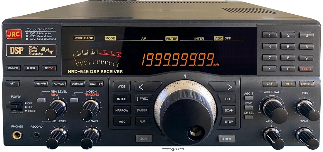 1998 |
JRC NRD-535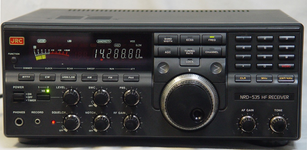 1991 |
JRC NRD-525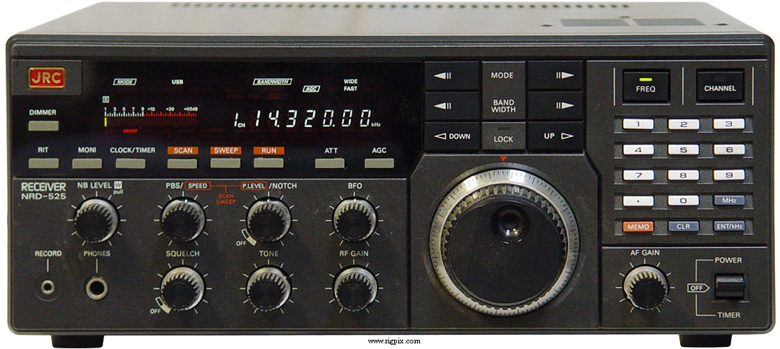 1986 |
JRC NRD-345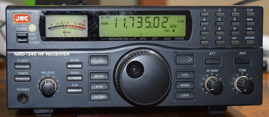 1997 |
| JRC NRD-515 515-Tower and video 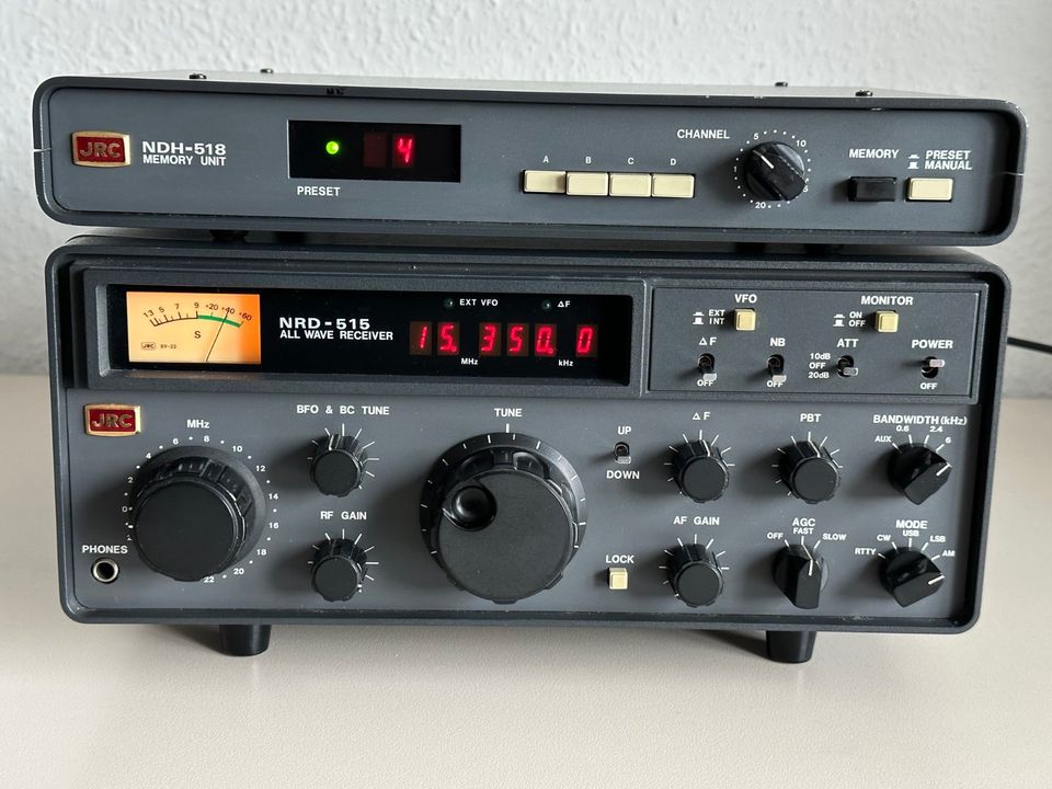 1979 |
JRC NRD-505 1977 |
JRC NRD-371 prototype, never wend in production ICOM was 80% cheaper 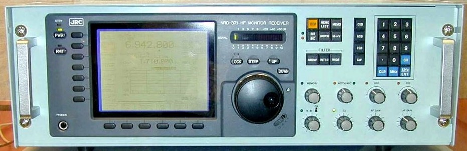 same for Ethernet LAN NRD-383 version |
JRC NRD-630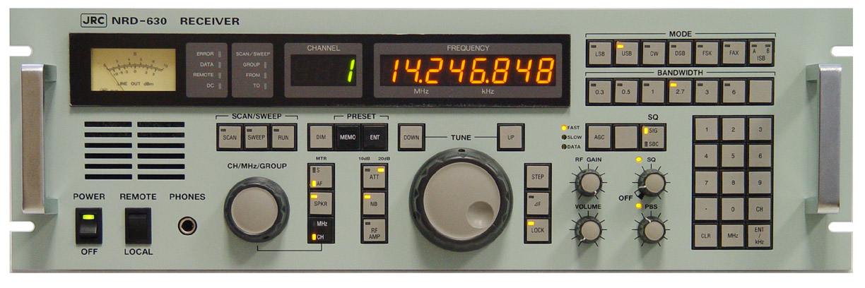 2007 |
JRC NRD-730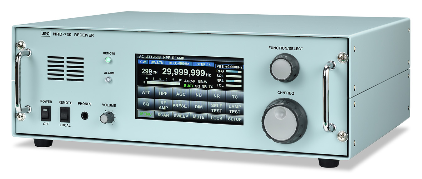 remote controlled boxed version NRD-740 |
JRC NRD-301A German FUNK test PDF 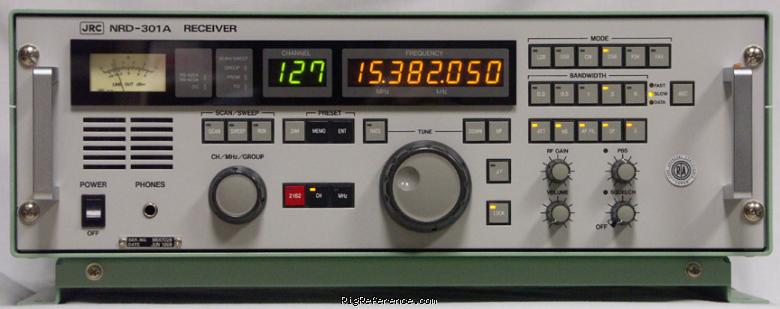 1996 |
JRC NRD-302A update NRD-301A 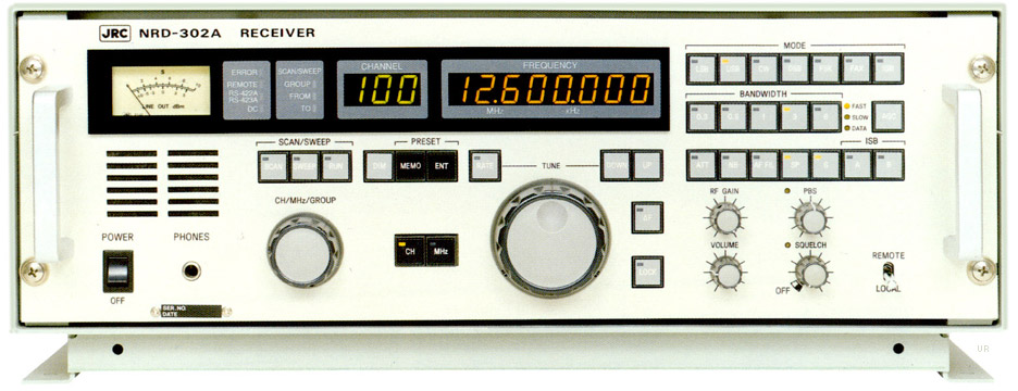 1996 |
JRC NRD-240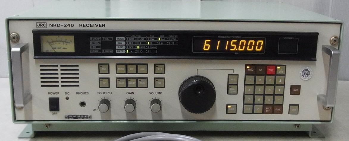 1990 |
JRC NRD-220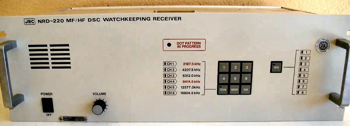 Digital Selective-Calling (DSC) Distress (Radio) Watchkeeping receiver 1990 93? |
JRC NRD-95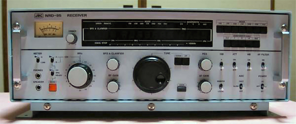 1983 |
JRC NRD-93L 1984 |
JRC NRD-92M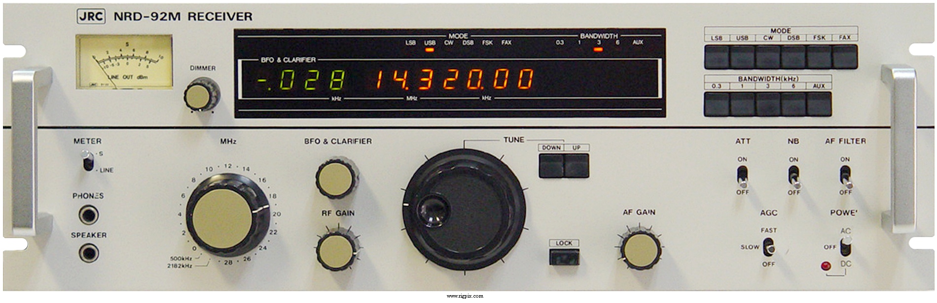 1984 |
JRC NRD-91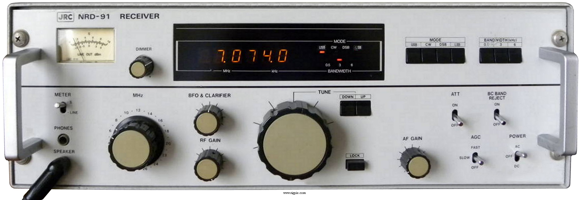 Rack mount channel version NRD-253 1984 |
JRC NRD-75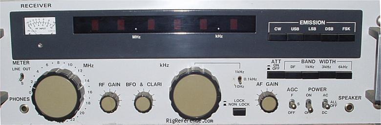 1978 |
JRC NRD-73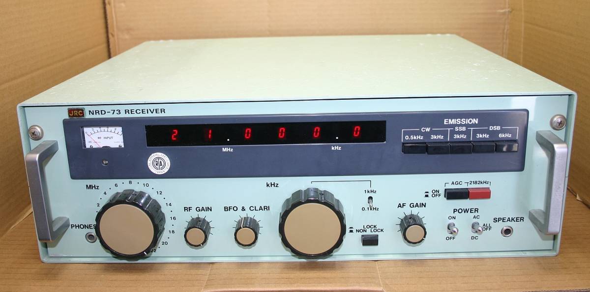 1978 |
JRC NRD-72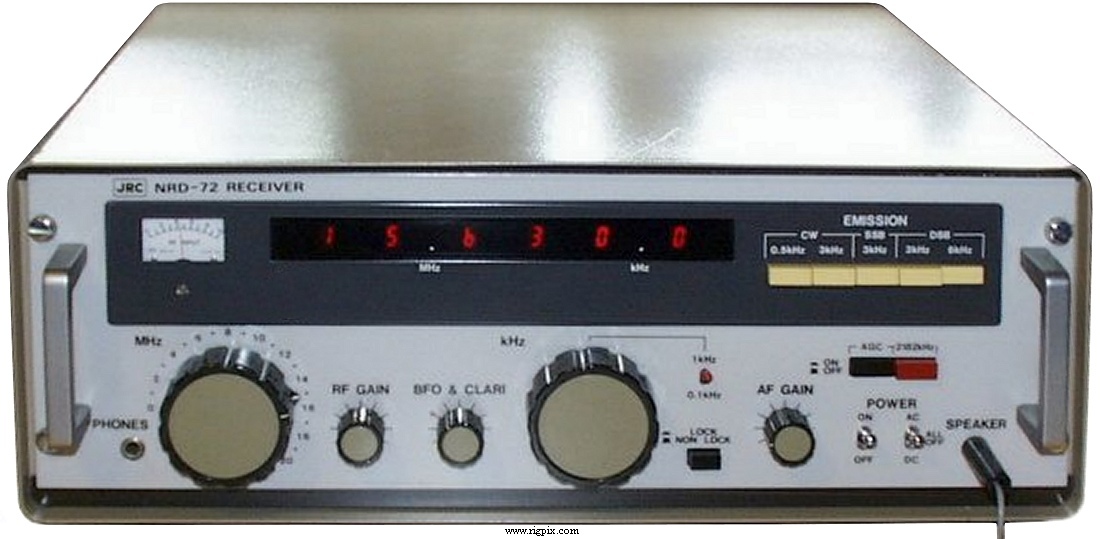 1979 |
JRC NRD-71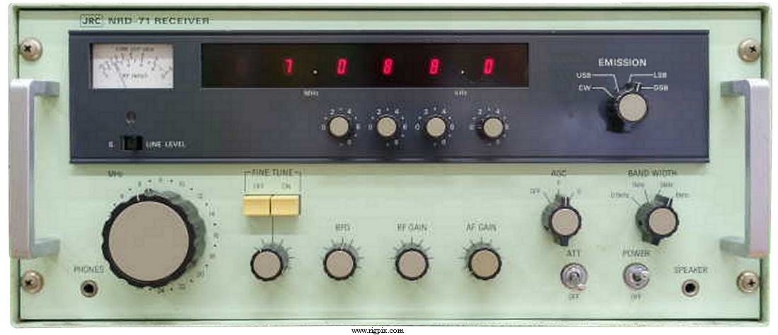 1978 |
JRC NRD-66 image from video still 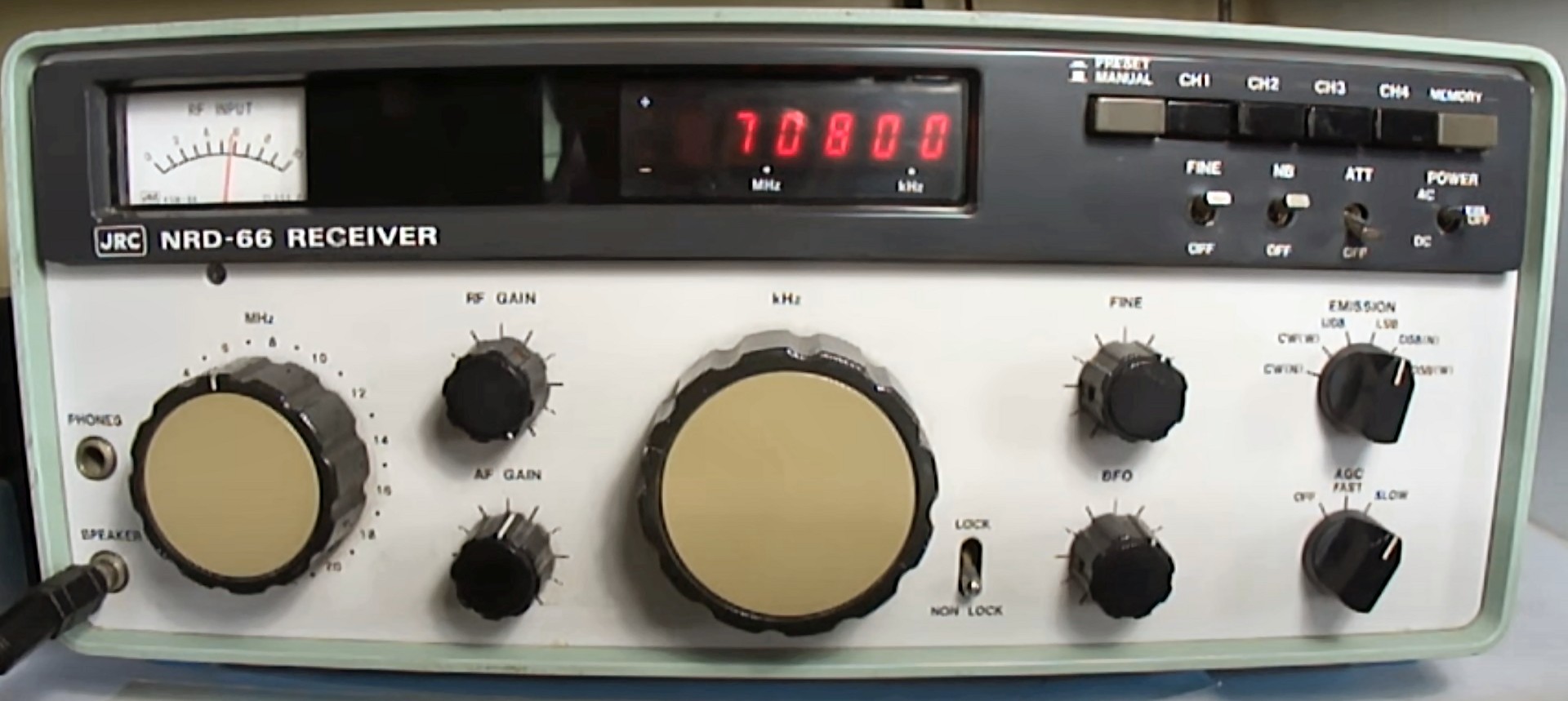
missing link between 505 and 515 Internal 505, ext. 515 looks Compare layout and (mem) switches with the NRD-505 1981 |
JRC NRD-61A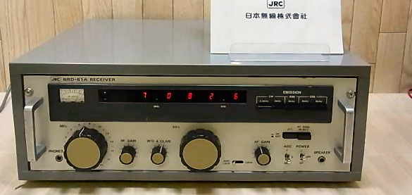 1977 |
JRC NRD-36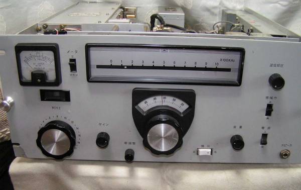 Remote version NRD-1 1972 |
JRC NRD-30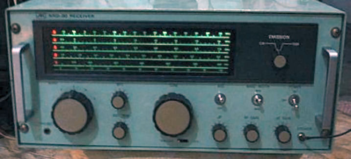 JRC NRD-20 Still from video 1976 |
JRC NRD-15A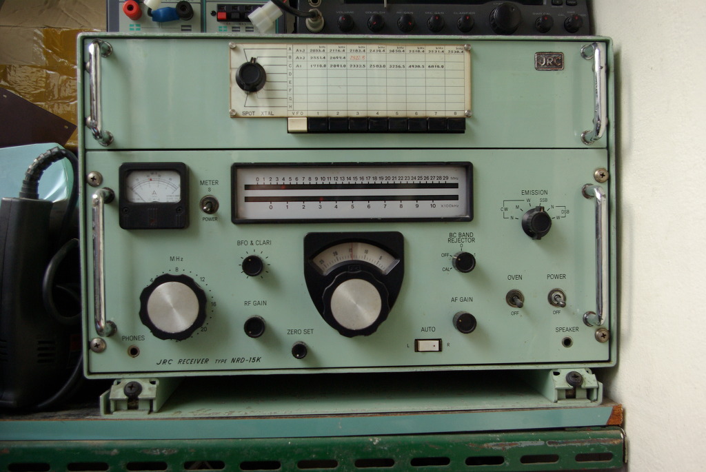 1970 |
JRC NRD-15K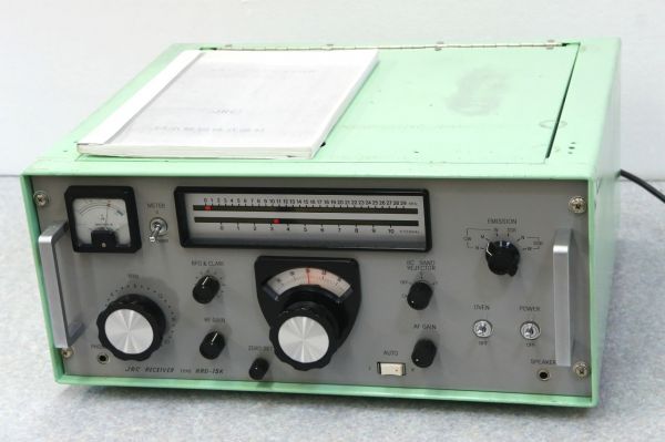 |
JRC NRD-11E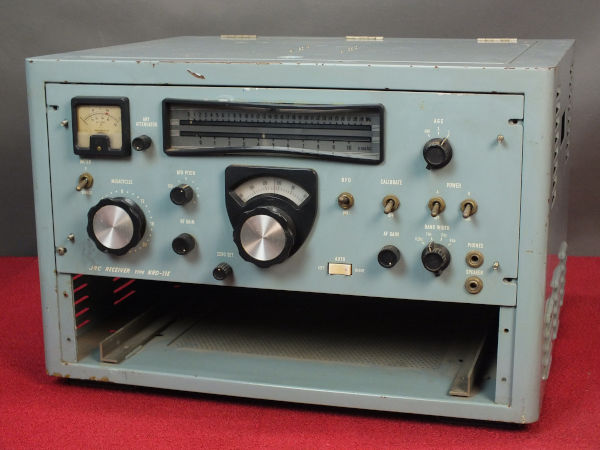 1966 |
JRC NRD-10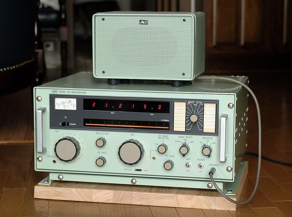 1972 |
JRC NRD-10 different version 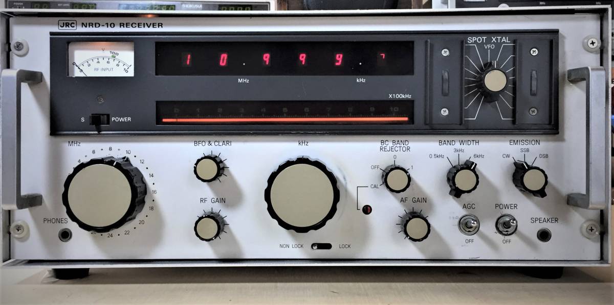 1972 |
JRC NRD-3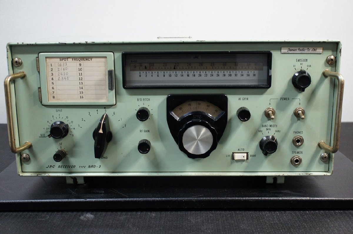 1968 |
JRC NRD-2K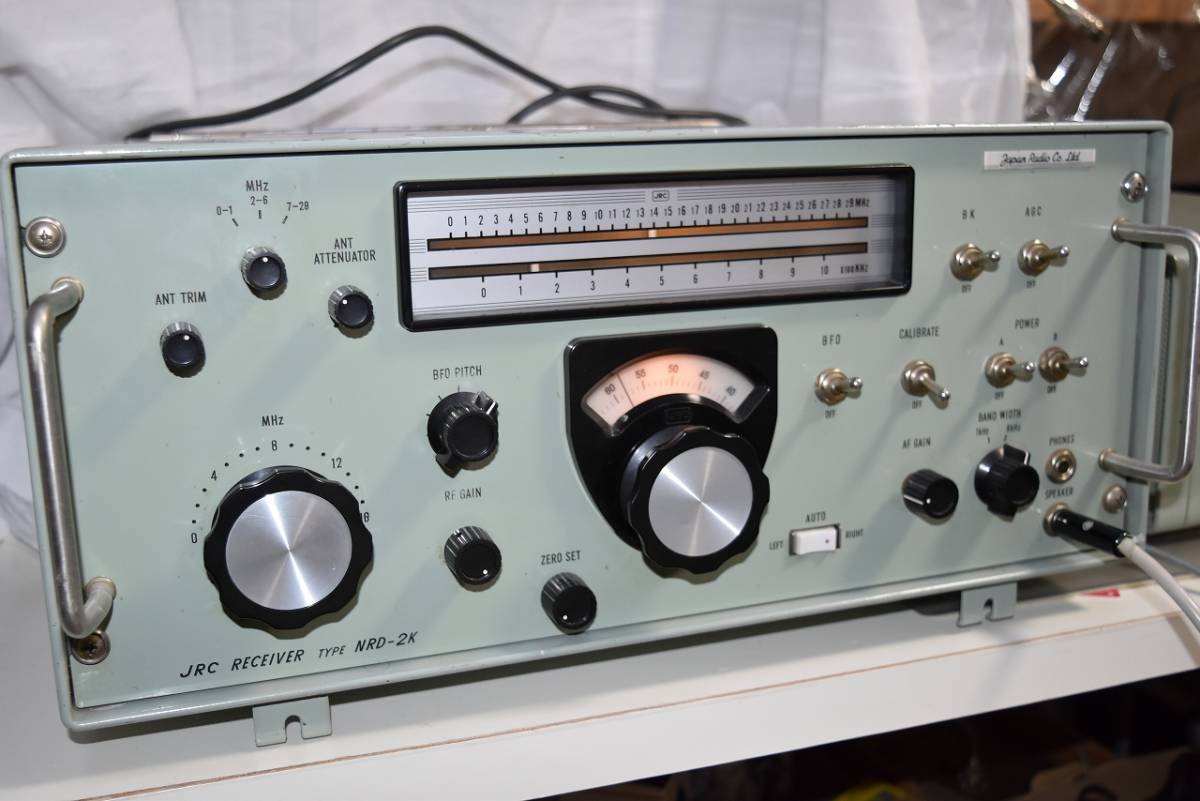 1967 |
JRC NRD-2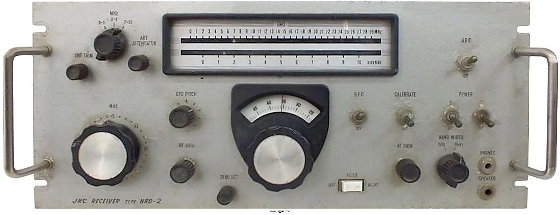 1967 |
JRC NRD-1EL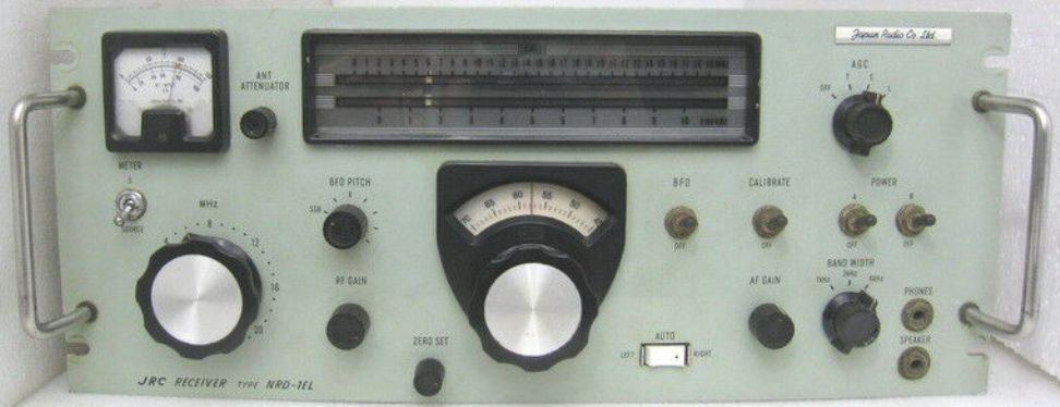 older version NRD-1E 1965 |
newer version JRC NRD-1B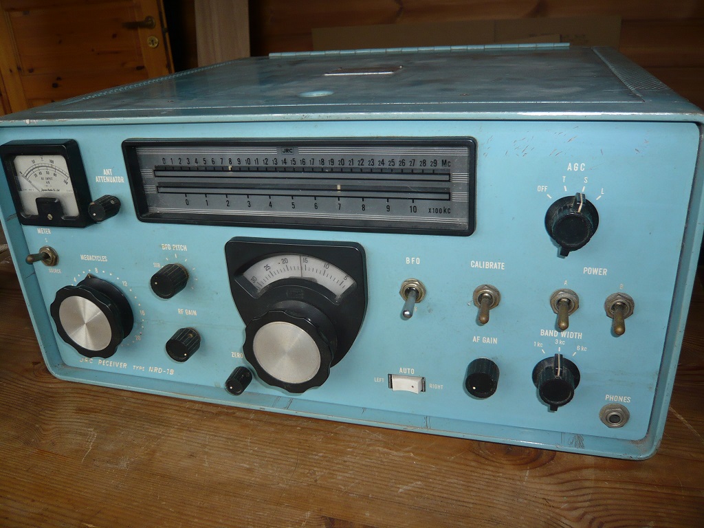 1965 |
JRC NRD-1001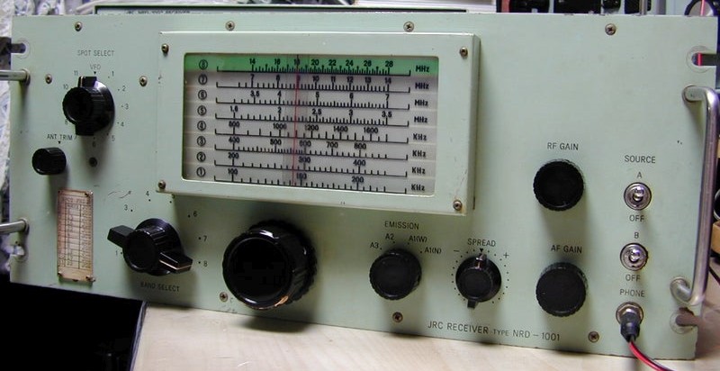 1981 |
JRC NRD-1002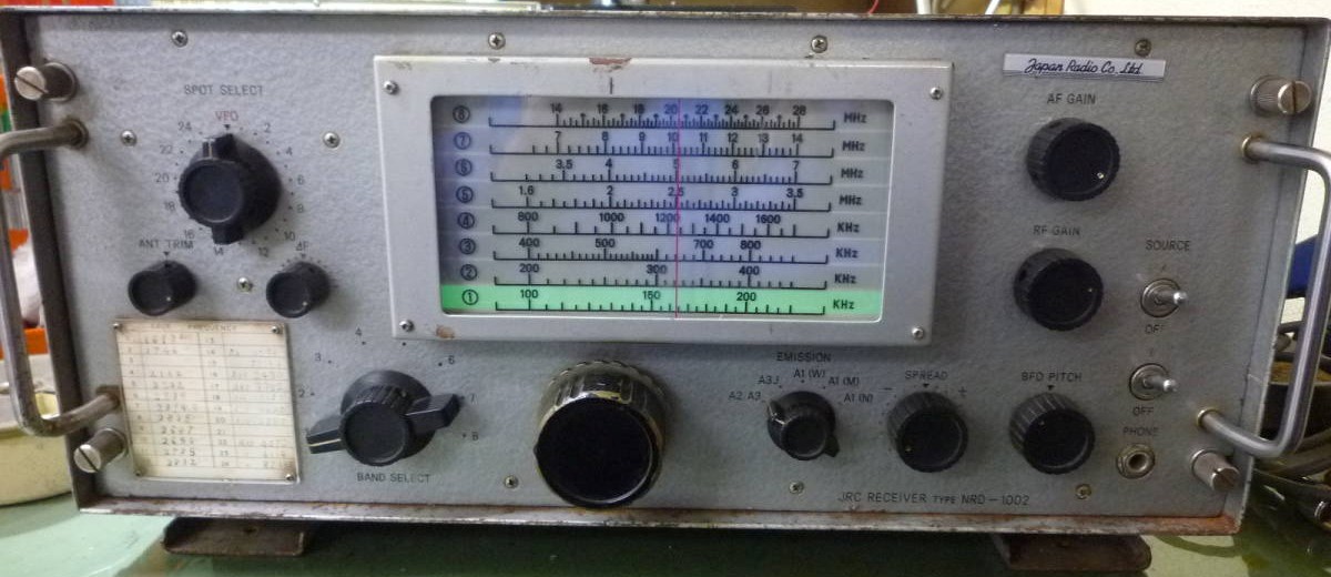 1971 |
JRC NRD-1003A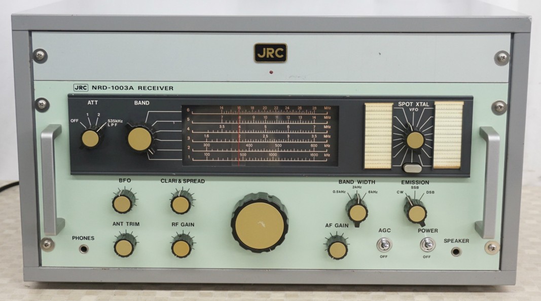 1978 |
JRC NRD-1010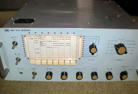 NRD-1010S (from 1977) is with synth VFO 1974 |
JRC NRD-130A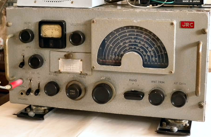 |
JRC NRD-1050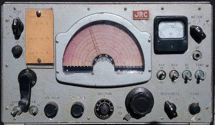 |
JRC NRD-1051C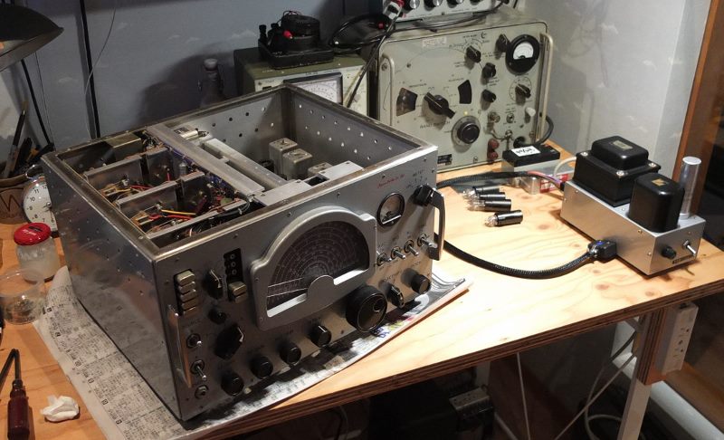 |
JRC NRD-1060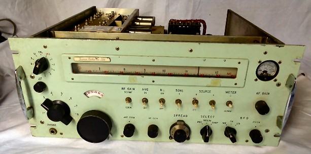 |
JRC NRD-1107D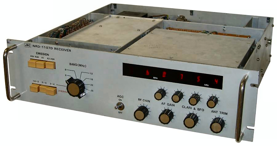 1977 |
|
And here is another special case. Many thousands of R-388/URR or 51J-3 receivers were built by Collins from 1950 up to about 1962 for military RTTY puposes. Japan Radio Co. received the Collins R-388/URR or 51J-3 license around 1964 for the local (ship) market. This has become NRD-143 from JRC. Notice how the front panel differs little from the original. A technically derivative of the NRD-143 /R-388 is the NRD-103 with motor control! It was much too expensive and quickly followed by the NRD-1. |
Collins' R-388/URR or 51J-3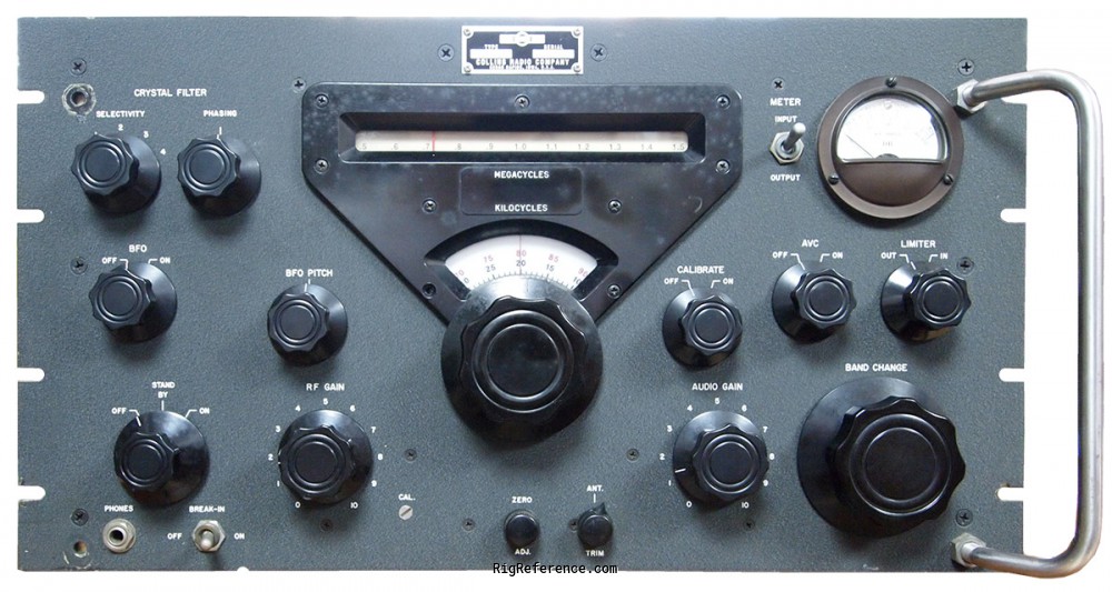 advertising brochure 1951 |
JRC NRD-143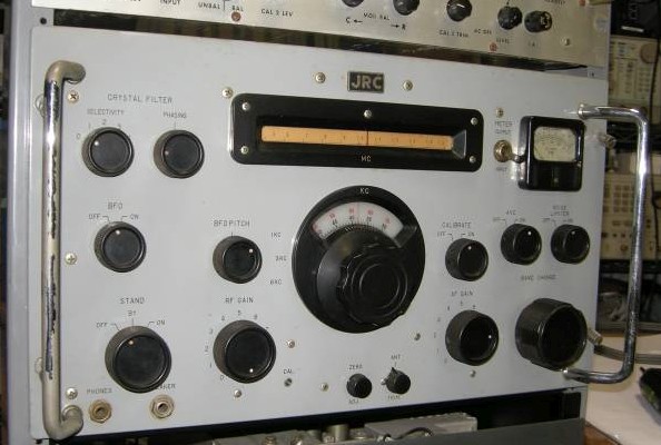 1954 |
JRC NRD-103 1958 |
Repair of a blown NBD-500, or better: a complete rebuild
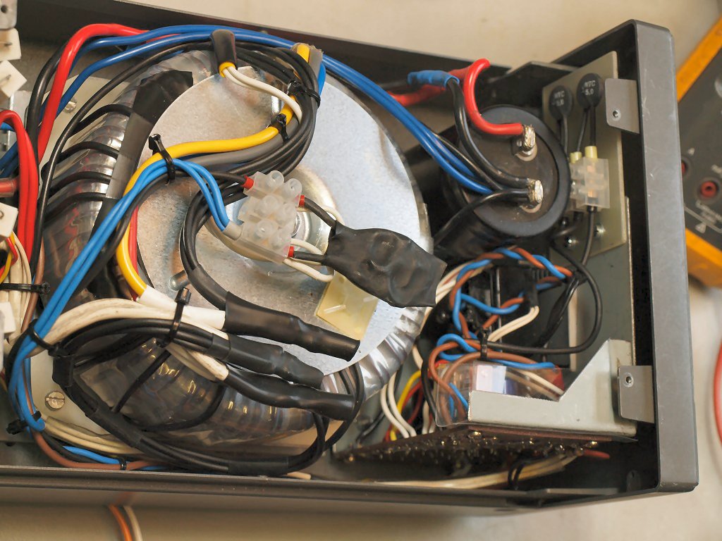
| Repair of a NBD-500 burnt out supply after lightning flash-over in the transformer. Apart from also a lot of damage in the JST-100. Is it hopelessly damaged? Or is there any chance for success? A "standard" transformer is simply not available, so an attempt was made to place a hughe modern mains toroid transformer in the cabinet. To avoid big mounting bolts sticking out of the cabinet and maintain airflow, an assembly seat was made for flat / horizontal mount. This also doesn't obstruct the normal airflow slits. Vertical mount didn't fit at all. Due to a big lack of space the circuit board also got a different position. Also added a set of inrush reducing NTC R's and a VDR to absorb switch-off spikes. The switch-on with a relay is now realised with a much safer approach. I used a little second low voltage transformer to keep the on-off switch circuit separated from hot mains. The toroid manufacturer output already had taken account for voltage drop, I also did when ordering a Amplimo 88043 toroid with 2x 17V AC. So the voltage was a little too high!! To reduce heat a negative winding is added (4 wires 1.5 sq. mm in parallel) to lower the secondairy output a little. By using 0.5 V per winding, I added 3 windings to reduce it with 1.5 V AC. It seems also possible now to use a toroid with 2x 15V AC and to ADD one or two windings if a little higher voltage is needed!
Take care: the NTC's become HOT, use a glassfiber cover board, and the VDR might explode, so encapsulate it in shrink tube. See the pictures below. Epilog: the mains voltage tracks crawling through the circuitboards inside the JST-100 is/was unwise by design. The tracks were all vaporised. And a flashover in the on-off switch to the circuit of the 74LS123. This IC was also blown, happily not more. One on-off switch section was for mains, the second for internal on-off (timer-)control. By using an additional modified small (adapter) transformer for making the 12V DC and a new low voltage relay (with 16 amp contacts!) for the on-off circuit it is a lot safer now. The extra transformer is situated between the big electrolyte and the board, it's a small black block with removed mains contact pins. The new on-off circuit is galvanically separated from everything, but has a static discharge to ground! See the extra PDF drawing, made graphically with original JRC symbols. Now it looks like JRC drew it themselves! And YES, all is working again! |
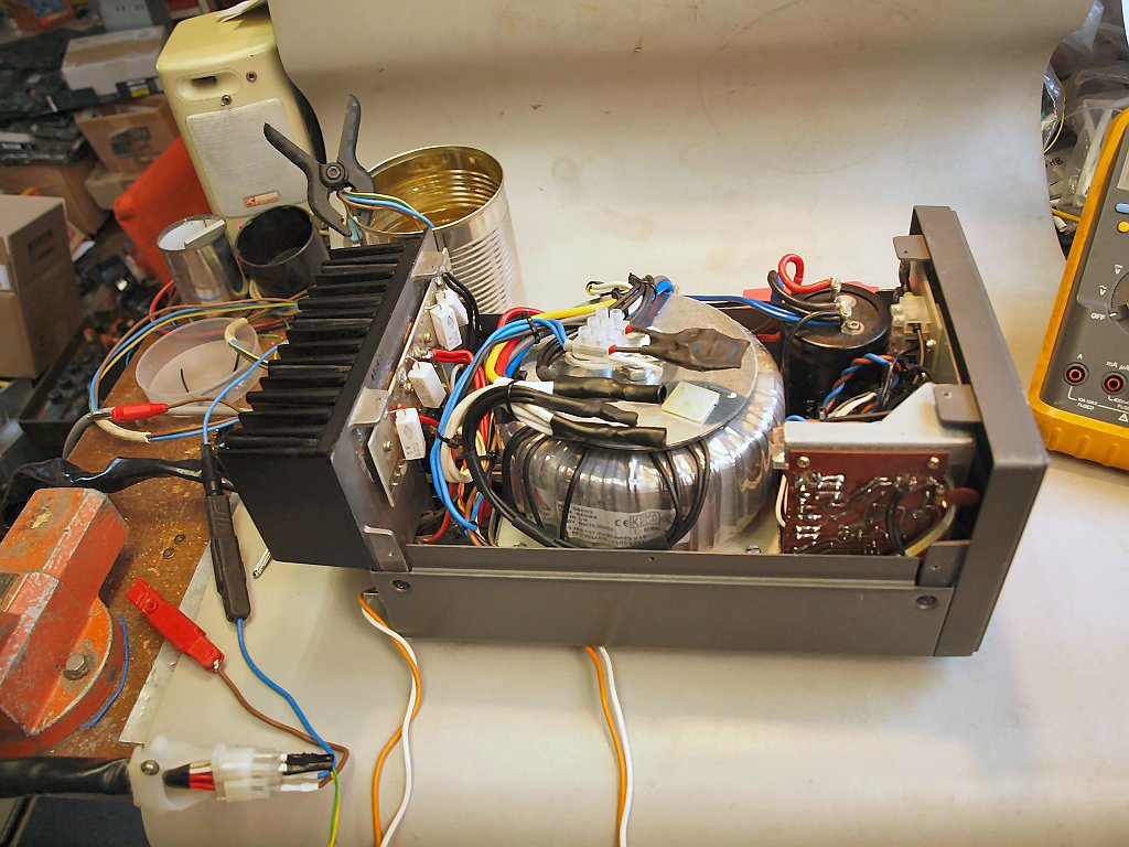
Top view, the tin can has a car bulb in water and a light shield = 2x 60W dummy load. It's an adjustable 2.5, 5 or 10 Amp dummy! |
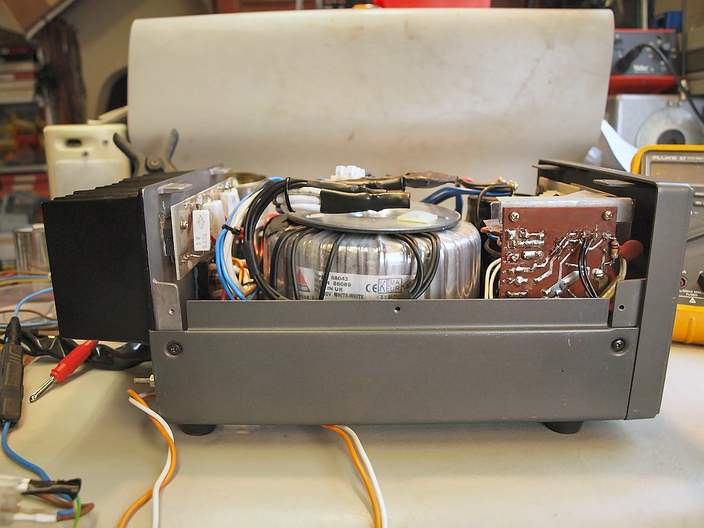
Side view, see 4x parallel negative winding |
Watch new location control board and mounting bracket, VDR and NTC's |
|
|
|
| JRC-extra.htm by Walter - PE1ABR - 2024-03-04 |
