|
|
|
|
|
|
|
|
|
A measure setup for 455 kHz IF transformers. This part is a spin-off of the IF filter measure setup. |
Nederlands? |
| For the planned construction of an 455 kHz IF extension for a professional receiver I also need, except a few well-tested IF-filters, a few non standard 7 mm 455 kHz IF-transformers.
Because there are more than a hundred in the junkbox of which the specifications are not exactly known, the desire was, same as for the IF filters, to create here too a simple measuring arrangement, without the risk to destroy the tiny transformes too easy (f.i. pulling a leg out...). A simple Q- and winding ratio test is what I'm thinking off. The tiny transformes should also be tested with some form of load, not only to obtain an impression of the winding / Z ratio, but also to see the effect on the Q damping from an actual load-Z. Then almost naturally the application area follows.... A first preparation is "ohmic" measure to determine the location of the tap connection, which is usually at the "cold" side of the primary. And: is there a secondary?? And a parallel Cap? To be determined by the measured value of the secondary winding-R sometimes you can make already a guess about the application use: is it a transistor "base" side or something else. (very low < 1.0 Ohm for a transistor base connection, e.g. lots higher is for a filter Z or detector connection). |
 |
|
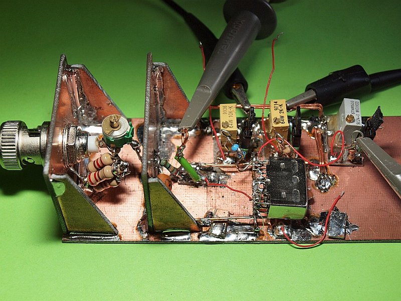
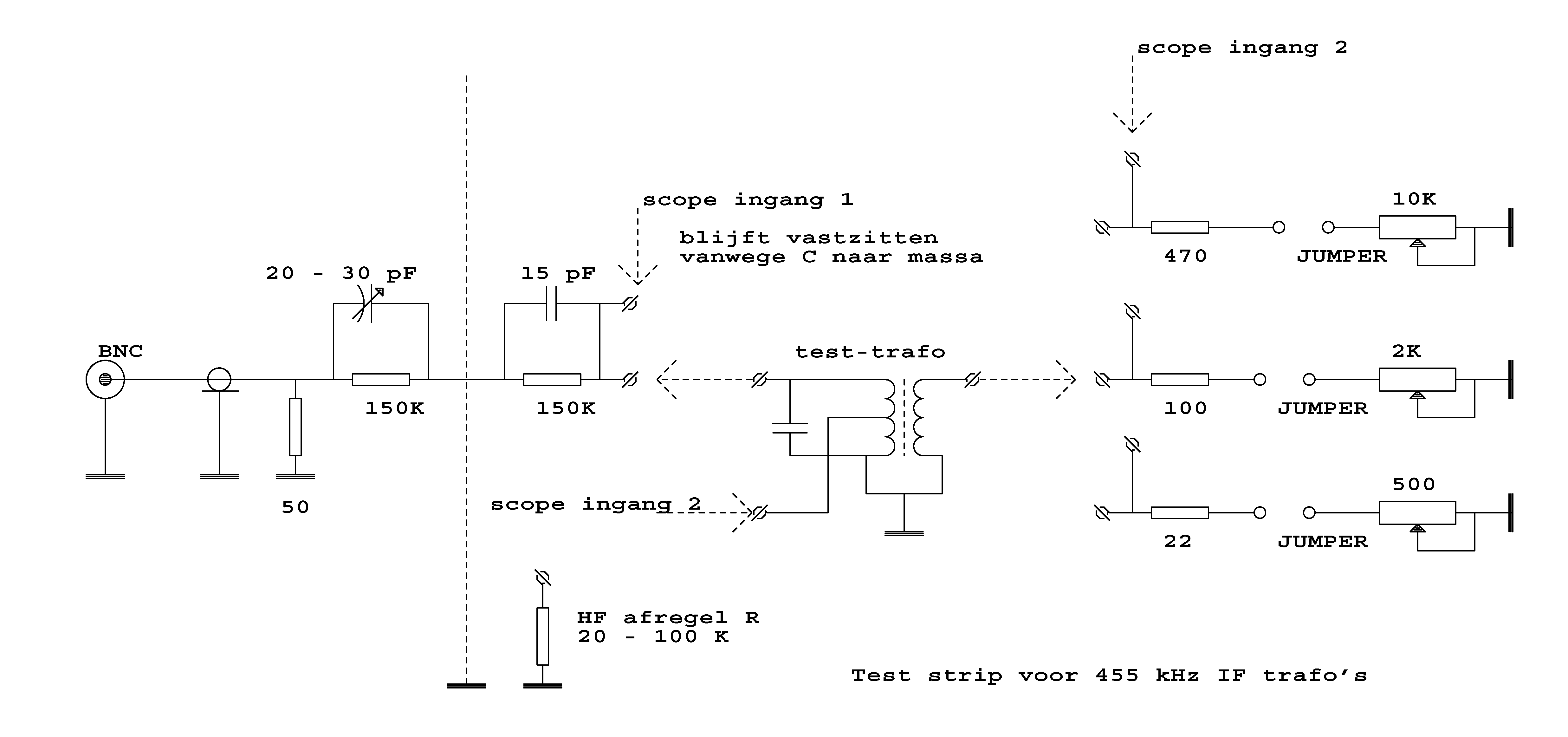
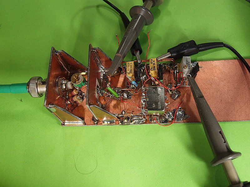
In manufacturers datasheets (Toko, Murata) I saw that IF transformer measuring was done from a very high Z directly on the hot side of the resonant circuit. I will do that too. Further: I had no intention using another series R for any type of transformer, a compromise is a common feeding series-R of 300 Kohm. Parallel with a small Cap of about 7 to 10 pF total for frequency-dependant alignment tuning. Once again the problem arose of HF leakage from the generator terminal directly to the measuring circuit, so this R is split into 2 equal parts. Half (150K) on one side of the shielding and the other half to the measuring point. In the middle of the shield is a small capacitance-free throughput patch (low para-C). So 2x 150K, with, on one side, a fixed C of about 15 pF, on the other side a 20 to 30 pF trimmer where the HF compensation alignment can be done. The alignment load is 20 to 100 Kohm along / parallel with the parasitic capacity of an oscilloscope probe and then feed 100 Hz, 1 kHz, 50 kHz, etc., up to 455 kHz through while ”almost” equal level is adjusted. Not extremely important in this structure. Keep in mind: the scope-probe should stay connected for proper capacitive load! How much loading of the circuit Q? That has become somewhat "guesswork". We will primarily feed signal through a series-R of 300 K. Secondary, we have an expected Z of 100 ohms up to 10 to perhaps 20 K ohms. Ultimately there are three pieces of isolated PCB-clad with on each a multi-turn potentiometer and a series R of ± 5% of that value, so that turned all zero, and problems with it (just did not think that he's got to zero ...), cannot happen. And it can be switched off with a jumper, you can switch the R "on / off" and study the effect of it. The values of the pot's are 10K, 2K, and 500 Ohms, corresponding series R's 470, 100 and 22 ohm. There is also a wire-eye turned to the R so we can still tie a probe to it. NOT to the weak transformer pins! What limit boundaries (ratio's) for the collapse of the Q we keep to, between no load and a proper ballast? Chosen so as to load until after the 300K R (the main feeding R) the level collapses to e.g. 50% = -6 dB on the resonant circuit. See the picture and the sketch (in Dutch) to get an idea. |
 High resolution version in a PDF |
 |
|
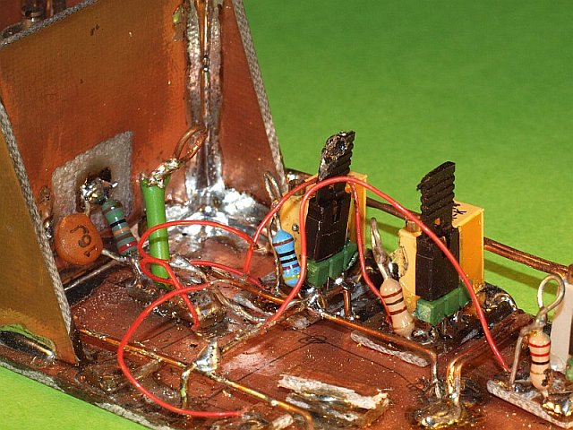
On the ground plane there are again a number of raised ground wires to solder transformers on with their mass tab. And a raised support (2 layers PCB) under the transformer spot to rest on. To the sides of the module (so on both sides) a pair of thicker wires to click the probe ground to. The transformer connections to the HF feed-R, and also for the coil-tapping's to the measurement points and and to the ballast-R sets are connected with very thin teflon wire wrap wire at the edge of the strip. Sticking gently (with solder) is done fast to the small pins and thus we do not ripoff one leg so easy of the transformer. Take a look at the zoomed-in picture: |
 |
|
Because my LF generator can deliver tens of volts, I could accidentally burn-out a 50 ohm 1/8 watt terminator easily. That is why the terminator is made more robust with 4x 220 ohm 1/2 watt R's in parallel. To finetune the resulting impedance value somewhat (now 55), I have added a 680 ohms R in parallel. And also this has become a very handy accessory..... Walter Geeraert PE1ABR |
 Back to the 455 kHz index page
 |
|
| The IF-transformer measure setup Compilation by Walter - PE1ABR - 2022-03-24 |